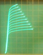
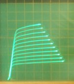
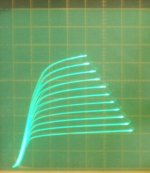
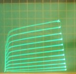
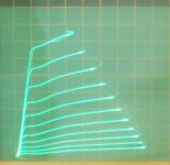
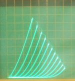
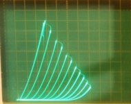
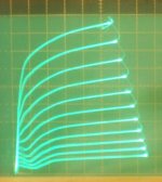
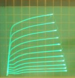
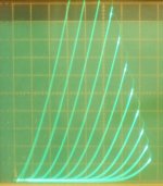
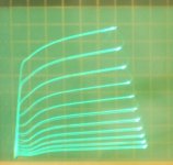
And here is the GU-50 in "Crazy Drive" mode.
(g2 driven by voltage and Rg2g1 from g2 to g1, and Rg1k from g1 to cathode)
50 mA/div Vert., 50V/div Horiz. for all.
1) g2g1 7V steps down from +162V, +20V on g3, Rg2g1 = 2.83K, Rg1k = 2.58K
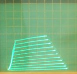
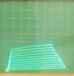
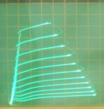
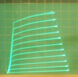
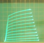
2) g2g1 7V steps down from +120V, +11V on g3, Rg2g1 = 2.83K, Rg1k = 2.58K
3) g2g1 7V steps down from +120V, 0V on g3, Rg2g1 = 2.83K, Rg1k = 2.58K
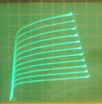
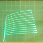
4) g2g1 7V steps down from +71V, +11V on g3, Rg2g1 = 2.83K, Rg1k = 2.58K
It might be possible to tune up Rg2g1 and Rg1k a little better, since I couldn't check the high and very low current ranges together easily. (10 turn pot to spin around on the +Vg2 supply)
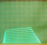
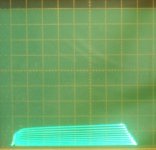
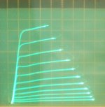
(Oops, forgot these for g2 drive in above post)
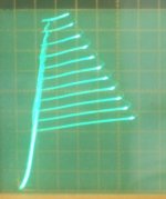
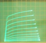
5) g2 drive, 7V steps down from 70V, +15V on g3, 50 mA/div Vert.
6) g2 drive, 7V steps down from 70V, +15V on g3, 10 mA/div Vert.
seems to like a little more +Vg3 at higher current
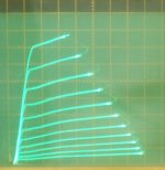
(g2 driven by voltage and Rg2g1 from g2 to g1, and Rg1k from g1 to cathode)
50 mA/div Vert., 50V/div Horiz. for all.
1) g2g1 7V steps down from +162V, +20V on g3, Rg2g1 = 2.83K, Rg1k = 2.58K
2) g2g1 7V steps down from +120V, +11V on g3, Rg2g1 = 2.83K, Rg1k = 2.58K
3) g2g1 7V steps down from +120V, 0V on g3, Rg2g1 = 2.83K, Rg1k = 2.58K
4) g2g1 7V steps down from +71V, +11V on g3, Rg2g1 = 2.83K, Rg1k = 2.58K
It might be possible to tune up Rg2g1 and Rg1k a little better, since I couldn't check the high and very low current ranges together easily. (10 turn pot to spin around on the +Vg2 supply)
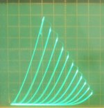
(Oops, forgot these for g2 drive in above post)
5) g2 drive, 7V steps down from 70V, +15V on g3, 50 mA/div Vert.
6) g2 drive, 7V steps down from 70V, +15V on g3, 10 mA/div Vert.
seems to like a little more +Vg3 at higher current
Attachments
-
 rsz_gu50_g2g1_7vs_162v_+20v_283k_258k_50_50.jpg53.3 KB · Views: 591
 -
 rsz_gu50_g2g1_7vs_120v_+11vg3_283k_258k_50_50.jpg57.2 KB · Views: 592
 -
 rsz_gu50_g2g1_7vs_120v_0vg3_283k_258k_50_50.jpg57.5 KB · Views: 578
 -
 rsz_gu50_g2g1_7vs_71v_+11vg3_283k_258k_50_50.jpg60.7 KB · Views: 577
 -
 rsz_gu50_g2_7vs_70v_-15vg3_10ma.jpg66.7 KB · Views: 107
 -
 rsz_gu50_g2_7vs_70v_-15vg3_50ma.jpg61.2 KB · Views: 574
Last edited:
How about Russian TV tubes...6P13S and 6P44S..for screen drive mode?
EL508 (PL508) is very close.
If one were looking for a replacement for the 7868 tube, I would use the 6HB5 with the grid 2 voltage reduced down to approx. 76V. (lets say 80 V to be safe)
It's rated 18 Watts, but has a plate size equal to 24 Watt Sweep tubes (or about 35 Watt for audio tubes).
It requires about twice the heater current at 1.5 Amp/ 6.3V however. (versus 0.8 A for the 7868)
It would probably produce twice the power output of the 7868 if the OT Zpri were reduced to 3.3K, but that would require a beefier (2x current) B+ supply then.
7868 gm = 10.2K at 60 mA, plate knee = 180 mA for Vg2 = 300V, Rp = 29K
6HB5 gm = 9100 at 50 mA => 10.2K gm at 60 mA, plate knee = 180 mA for Vg2 = 76V, Rp at 60 mA would be 9740 Ohm (so 3x better damping factor)
So its a "drop in" replacement with Vg2 lowered to 80V (reg.), a socket change, and 2x the heater current.
-----------------------
Hmmm, that EL508 looks like a good 7868 replacement too, same heater current. Just reduce the Vg2 down to 140V for the same plate knee, and a socket change.
Last edited:
6GB5/EL500 would be another good replacement for the 7868 tube, since it is (very) near identical in specs to the 6HB5.
It requires 1.38 A/6.3 V for the heater (versus 0.8 A for the 7868). Using +76V for Vg2 also gives a plate knee at 180 mA like the 7868 (at +300Vg2). The gm at 60 mA would be around 9000 (versus 10200 for the 7868).
It requires 1.38 A/6.3 V for the heater (versus 0.8 A for the 7868). Using +76V for Vg2 also gives a plate knee at 180 mA like the 7868 (at +300Vg2). The gm at 60 mA would be around 9000 (versus 10200 for the 7868).
Last edited:
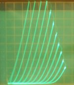
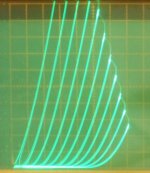
Here are some curves for the 12BQ6GTB tube.
All are at 50 mA/div Vert., and 50V/div Horiz.
1) GE 12BQ6GTB normal pentode mode, 2.8V steps on g1, Vg2 = 158V
2) GE 12BQ6GTB Triode mode, 7 V steps on g1
3) GE 12BQ6GTB g2 drive, 7 V steps down from 158V
4) GE 12BQ6GTB g2 drive, 7 V steps down from 88V
5) GE 12BQ6GTB g2g1 Crazy Drive, 7 V steps down from 130V, Rg2g1 = 2.45K, Rg1k = 2.45K
6) GE 12BQ6GTB g2g1 Crazy Drive, 7 V steps down from 73V, Rg2g1 = 2.45K, Rg1k = 2.45K
7) Raytheon 6BQ6GA normal pentode, 2.8V steps on g1, Vg2 = 148V
8) Raytheon 6BQ6GA Triode mode, 7 V steps on g1
9) GE 12BQ6GA normal pentode, 2.8 V steps on g1, Vg2 = 143V
10) GE 12GE5 normal pentode, 2.8V steps on g1, Vg2 = 148V
The GE 12BQ6GA internals look just like the GE 12GE5 internals (also same as 6/12JN6, 6GV5), 17.5 Watt tubes. The Raytheon 6BQ6GA is also similarly large plated (slightly bigger even), but a different square boxy appearance.
Attachments
-
 rsz_12bq6ga_ge_g1_28vs_143v_50_50.jpg63.1 KB · Views: 97
 -
 rsz_6bq6ga_t_7vs_50_50.jpg60.1 KB · Views: 100
 -
 rsz_6bq6ga_g1_28vs_148v_50_50.jpg60.6 KB · Views: 108
 -
 rsz_12bq6gtb_g2g1_7vs_73v_50_50.jpg55.8 KB · Views: 106
 -
 rsz_12bq6gtb_g2g1_7vs_130v_50_50.jpg53.7 KB · Views: 99
 -
 rsz_12bq6gtb_g2_7vs_88v_50_50.jpg59.2 KB · Views: 94
 -
 rsz_12bq6gtb_g2_7vs_158v_50_50.jpg58.7 KB · Views: 103
 -
 rsz_12bq6gtb_t_7vs_50_50.jpg64.7 KB · Views: 108
 -
 rsz_12bq6gtb_g1_28vs_158v_50_50.jpg60 KB · Views: 108
 -
 rsz_12ge5_p_28v_148v_50_50.jpg58.4 KB · Views: 97
Last edited:
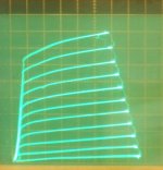
Here are some curves for the 12L6 tube.
All are at 20 mA/div Vert., 50V/div Horiz.
The Haltron tube Anatoliy just sent looks somewhat poor in the knees. But he had sent me another Haltron 12L6 some while back, so I did that one too (pics 5 thru 8), and it looks much better.
1) 12L6 in normal pentode, 1.5V steps, Vg2 = 110V
2) 12L6 in g2 drive, 7 V steps down from 110V
3) 12L6 in Crazy Drive g2g1 mode, 5 V steps down from 53V, Rg2g1 = 2.22K, Rg1k = 1.35K
4) 12L6 in triode mode, 5 V steps
5) 12L6 in normal pentode, 1.5V steps, Vg2 = 110V
6) 12L6 in g2 drive, 7 V steps down from 110V
7) 12L6 in Crazy Drive g2g1 mode, 5 V steps down from 53V, Rg2g1 = 2.22K, Rg1k = 1.35K
8) 12L6 in triode mode, 5 V steps
Interesting that Crazy Drive or Triode mode are able to fix up the poor curves (knees) for the 1st tube.
Attachments
-
 rsz_12l6_g1_15vs_110v_20_50.jpg66.9 KB · Views: 110
 -
 rsz_12l6__t_5vs_20_50.jpg66.6 KB · Views: 107
 -
 rsz_12l6__g2g1_5vs_53v_20_50.jpg64.1 KB · Views: 104
 -
 rsz_12l6__g2_7vs_110v_20_50.jpg61.6 KB · Views: 91
 -
 rsz_12l6__g1_15vs_110v_20_50.jpg67.2 KB · Views: 102
 -
 rsz_12l6_t_5vs_20_50.jpg72.2 KB · Views: 100
 -
 rsz_12l6_g2g1_5vs_53v_20_50.jpg69.7 KB · Views: 93
 -
 rsz_12l6_g2_7vs_110v_20_50.jpg65.3 KB · Views: 98
Last edited:
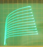
I also had an RCA 12W6 laying on the shelf here, which is an up-rated version of the 12L6, so I did some curves for it too. Then I found a Sylvania 12W6, pic 5) in pentode. Bad knees too.
1) RCA 12W6 in normal pentode, 1.5V steps, Vg2 = 110V
2) RCA 12W6 in g2 drive, 7 V steps down from 110V
3) RCA 12W6 in Crazy Drive g2g1 mode, 5 V steps down from 53V, Rg2g1 = 2.22K, Rg1k = 1.35K
4) RCA 12W6 in triode mode, 5 V steps
5) Sylvania 12W6 in normal pentode, 1.5V steps, Vg2 = 110V
Looks like the 12W6 could have used about 124V on g2 (instead of 110V) to equal the earlier 12L6 maximums for the g1 and g2 curves. And about 55V for the g2g1 Crazy Drive (instead of 53V).
Attachments
Last edited:
Ran out of time to edit above.
Crazy Drive fixed up the above Sylvania 12W6, with the bad knees, so it looks similar to the RCA 12W6 with Crazy Drive. (just like it fixed up the 1st 12L6 too.) Impressive. I don't know how it does this.... (since the g2 curves are bad there too. See the 1st 12L6.)
I've also noted (in general) that Crazy Drive seems to revert to the g1 curves gain (or spacing) at very low plate current. I guess the g2 gain gives out 1st. This is probably good, since it means that the P-P crossover region will be similar to g1 drive, which is usually benign for crossover overlap.
Last edited:
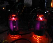
I got a strange surprise today. Don and I both decided based on 2 out of 2 tubes that the Korean 13GB5's that I have are junk. The Mullards that I have more of, are however, nice tubes.
I have an old HP power supply that puts out 650 volts at up to 1.7 amps, MUCH more for the 500 mS or so it takes for the current limiter to kick in. There is about 1000 uF of capacitance inside the unit directly across the output. The stored energy in this thing has blown electrolytics to pieces, vaporized resistors and PC board plating, executed several vacuum tubes in spectacular fashion, and set an OPT on fire.
I have a driver board that I just built. It is a totally new design with 7 mosfets and 2 vacuum tubes, that works well in LT Spice, but has been temperamental in real life. It has far too much gain, cranking out 150 volts P-P at 0.25% distortion from 0.25 volts P-P of input.....I'll fix that later, for now it's time to test it.
I wired the driver board up to a turret board configured for 13GB5's in G1 drive. Last weekend's experiments ended with a smoking mosfet and a resistor that got so hot it unsoldered itself.
After soldering the resistor back in, and fixing my wiring error, I tried again this morning. Something strange was going on. One of the 13GB5's would work for a while, then lose power. The current would drop off. After a cooling off period the cycle would repeat.....sound familiar? Except these were not the Korean tubes, these were Mullards. The disease followed the tube, so I shut the whole thing off and ate lunch.
This thing had been bugging me for over a week, so I decided to plug in a pair of the Korean junk tubes, set the power supplies on KILL and melt them.....just because I can!
SURPRISE!!!!! They are NOT DEAD yet. Yes, I tried two of these tubes when I got them, and blew one up. I cut it open and saw evidence of arcing. I put the other tube back in its box. That same tube (the box was torn) and another random tube was plugged into the test amp.
I wasn't planning to be nice, so I set the bias at 50 mA and 500 volts. YES 25 watts of idle power on a 17 watt tube......no glow, so I let them cook for a while, then applied signal......WTF, the distortion at 1 watt is 0.22%. 10 Watts, 0.43%....CRANK. clipping happens at 103 watts.....OK let's see how long it takes for one to blow.....fire extinguisher standing by.......15 minutes later I smell something cooking.....it's the load resistor, OK, power off.
After 10 minutes or so, I powered back up, and reset the idle current to 30 mA. The distortion was still about the same. Power off again. I have some new simulations for lower gain and lower distortion, but I need to change several parts.
Pictures.....the tubes have a faint orange glow on one side of the plate. The camera sees IR as purple.
Attachments
Last edited:
I was about to smack the "bad" 13GB5 with a hammer, but I decided to retest it in the amp one more time. Yep, it's still NFG, but wait.....the heater is barely glowing. The ohmmeter says 14 ohms cold.....the other Mullards measure 3.8 ohms cold.....The lettering clearly says 13GB5/XL500, same as its brothers. Could it be a mismarked 27GB5? I connected it to a power supply and turned up the voltage......it lights up pretty good on 27 volts.....
Hmm, I wonder if that was the problem with the Korean 13GB5 I had. I have a couple of other tube types that seem to be mis-marked heater voltage versions, including one that doesn't officially exist. Tough finding a matched set.
Hmm, I wonder if that was the problem with the Korean 13GB5 I had
I don't know, but it is possible. I need to find the rest of them and run them through the test amp before I rip it up again. Last night's parts changes seems to be a step in the wrong direction. I only have 3 of the Korean version here in the basement lab, but there should be a dozen more or so in cold storage next door. Odds are there are more junk tubes in the batch.
I have a couple of other tube types that seem to be mis-marked heater voltage versions, including one that doesn't officially exist.
Most of the mis-marked tubes that I had were rebranded tubes. I had one where the original GE number did not match the new silk screened number.
There is a big problem with counterfeit parts today, but sometimes vendors just screw up.
I worked at Motorola in Florida for 41 years. During the mid 70's there were several of us building "home computers" that used the Motorola MC6800 chips. The factory was building BBT (Building Block Terminals) for radio paging. They were based on some other microprocessor (Intel maybe?). They got in a batch of MCM4116 memory chips from Motorola Semiconductor (Phoenix AZ). These are dynamic rams that come in a 16 pin DIP. The shiny new ceramic and gold RAM chips had 18 pins, but were clearly marked MCM4116xxx (xxx is the speed rating and I don't remember what it was).....UH these don't fit. Nobody in Phoenix had a clue. They agreed to find the right parts and FedEx them. We were to scrap the wrong stuff......
I had an idea, so I asked for a hand full of the wrong parts. I went home that night and wired a couple into my home PC. The mystery parts were MCM2114 STATIC rams, a part that Motorola didn't officially make yet, but Mostek did( MK2114)....An incident with a broken SEM and a couple of us working all night to fix it, had earned us a few favors in Phoenix, so after a few phone calls, the mystery parts were declared "samples" and they were ours.
My "home computer" started out as a SWPTC (Tiger audio amps) kit, and grew to fill a whole workbench. This monster would dim the lights when you turned it on, but had less processing power than a $2 PIC chip has today. Maybe 30 years ago, I donated it here....
Virginia Information
Yeah, I miss those computer hobby days. I used to have the Altair computer, then the later S-100 stuff. Belonged to an active computer club (with several IBM research members/spies). It was so easy to wire wrap up a custom interface back then with DIP chips and sockets on protoboards.
Then IBM's XT came along which destroyed the hobby market. (inside information was that it was crippled intentionally so it could never compete with big $ products) Now everything is incomprehensible INTEL hardware interfaces, 100MB+ software, and endless clog-up advertising on the WWW, with virus's lurking everywhere.
Hobbyists just learn software hacking now, really useful, NOT! We re-wrote/customized operating systems in assembler that fit in 64K Bytes. We had a shared memory system for multiple computers. Frequent surplus hunting trips to Boston to pick up mini computer peripherals (printers, mag tape, disks, tape readers/punches, X-Y plotters ....) and then we interface'd them to the micro.
Some hobbyist oriented association needs to re-establish a simple computer system with a use able prototyping interface, and operating with minimal software complexity (64K max OS, NO Microsoft!). A software interface link to the PC then for Web access, storage etc. I guess that looks similar to some signal processing boards.
I was about to smack the "bad" 13GB5 with a hammer, but I decided to retest it in the amp one more time. Yep, it's still NFG, but wait.....the heater is barely glowing. The ohmmeter says 14 ohms cold.....the other Mullards measure 3.8 ohms cold.....The lettering clearly says 13GB5/XL500, same as its brothers. Could it be a mismarked 27GB5? I connected it to a power supply and turned up the voltage......it lights up pretty good on 27 volts.....
Is there an etched Phillips code on the glass?
That should indicate whether it's an XL500 or a PL500.
There are code numbers, but I don't know what they mean
Good tubes
A53 Or3 A53 A51 Or1
45K1 48H1 45J4 X3E4 ?1L1
Mystery tube
JD3 (could be 1D3)
X4K1 (could be X4K4)
Good tubes
A53 Or3 A53 A51 Or1
45K1 48H1 45J4 X3E4 ?1L1
Mystery tube
JD3 (could be 1D3)
X4K1 (could be X4K4)
I have a fair number of 13GB5s as well. A lot of them are made in Holland, and these have a narrow graphite-looking band around the bottom of the envelope. I also have a good number with a wide green band around the bottom. Most of these are marked as Japan-made. I have a few with no band at all. and no heat radiator fins welded to the screen grid posts. No clue as to the origin of those. They are branded RCA, Sylvania, GE, Zenith, Magnavox, Raytheon, and a couple of other off-brands, with no obvious association of type with brand name. I haven't tried torturing any of them yet. I may do some in pentode mode, but not until I've tried some 6P41S, which don't need the pesky plate cap.
There are code numbers, but I don't know what they mean
Good tubes
A53 Or3 A53 A51 Or1
45K1 48H1 45J4 X3E4 ?1L1
Mystery tube
JD3 (could be 1D3)
X4K1 (could be X4K4)
Bingo:
A5(revision number) = XL500/13GB5
0r(revision number) = XL504
JD(revision number) = PL500/27GB5
X = Phillips Sittard factory.
4, probably a right angled triangle: Phillips Heerlen factory.
After that come some date codes.
The difference between the .L500 and the .L504 is in the ratings. The .L500 is rated at 12W (design centre) and 16W (worst condition), the .L504 at 16 resp 22.5W.
It is times like these that I feel so out of the element -- it is very good reading and educational... but wow, you guys are on a way higher level that I almost feel like boxing all the TV tubes I have up and shipping them out to you for testing.
- Home
- Amplifiers
- Tubes / Valves
- Those Magnificent Television Tubes