Thanks tubelab, one more question: at what approximate operating current and Vg2 voltage?The 6KD6 will do 150 watts easily on 650 volts with a 3300 ohm load.
Jun, limit to screen dissipation ratings, about 5 watts, so at 150 volts, that will be about 33mA max...http://www.nj7p.org/Tubes/PDFs/Frank/123-GE/6KD6.pdf
Thanks sir Tony...I'm preparing the power and Output trafo for this build so it's good to know.
limit to screen dissipation ratings, about 5 watts, so at 150 volts, that will be about 33mA max
The screen rating is a dissipation rating based on power dissipation averaged over time. If the average goes over 5 watts for long the screen grid will overheat, and bad things can happen.
The screen current in a sweep tube, or any pentode, is dependent on it's voltage, and the plate voltage. Since the screen voltage in a sweep tube in audio use runs about 150 volts, and the plate voltage runs 400 to 800 volts, the idle screen current will be low, 5 to 10 mA. When the amp is pushed hard, there will be periods of time when the plate voltage dips below the screen voltage. During these periods the peak screen current skyrockets. As long as the average current stays below 33 mA the tubes are happy, but the screen supply must be able of meeting the peak demands or distortion will result.
Looking at the plate curves for the 6KD6 you can see that with a screen voltage of 150 volts, the plate voltage will be about 30 volts for a tube current of 800 mA. At that time the screen will draw about 150 mA. This current is drawn only for the instant that sine wave reached the minimum point (assuming sine wave testing). At that point the instantaneous screen dissipation is 22.5 watts!!!!!! Remember this happens only briefly, and for half of an audio cycle the tube is cut off and the screen dissipation is zero.
Note that the plate voltage, and load impedance determines the peak plate current. I assumed 650 volts and 3300 ohms, which is probably beyond where most people will run them, but for sine wave testing, you are below 5 watts, and for normal music (just touching clipping) these peaks will be few and far between. A sweep tube amp of this power level (about 200 watts) will NOT tolerate long term operation when driven to square wave output, because the screen dissipation will be 22.5 watts / 2 (50% duty cycle).
Gentlemen;
how would you crazy-drive such a thingy like Eimac 4CX350A?
It's screen grid can dissipate up to 8W, while control grid is very fragile.
how would you crazy-drive such a thingy like Eimac 4CX350A?
It's screen grid can dissipate up to 8W, while control grid is very fragile.
Its not clear that Crazy Drive would work for linearizing HV tubes. Can only try it and see. The datasheet for the 4CX250R shows 2 Watts max diss. for grid 1 on page 2, and shows curves for grid 1 up to +20V on page 4. Max grid 2 diss. of 12 Watts.
You would have to try it with some meters to monitor grid 1 and grid 2 dissipation. Likely a high value resistor from grid 2 to grid 1 for Crazy Drive, maybe try a 50K 10 turn pot, then a 10K ten turn pot from grid1 to cathode. Some manual curve tracing (with plate power supply for 1000V+ and dummy load R) of plate current out versus grid2 Vin then to see the results. Variable 500V supply for sweeping grid 2. Will be tedious to adjust pots and repeat, over and over, to see if it will linearize. Maybe use a DC current probe for the plate current, and XY scope display of plate current versus Vg2. Manually sweep Vg2 quickly. Iteratively adjust the pots. The current probe could be placed at the cathode wire, with the screen grid feed wire through it too, to subtract that current out.
http://frank.pocnet.net/sheets/140/7/7580W.pdf
Last edited:
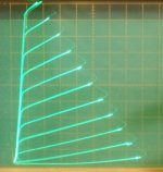
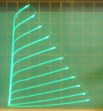
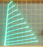
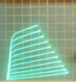
I haven't done any actual dist. measurements, but just from looking at the plate curves I'd say it removes from 50% to 90% of the 2nd harmonic curvature (depending on tube type). The lack of curvature remaining, even with-in the individual plate curves, as well as the very monotonic spacing between the plate curves, bodes very well for reduced higher harmonics.
Combine that with the reduced g2 drive swing required (about 23% less for 26LX6), making for much safer operation of the tube, and this is clearly a BIG WIN over normal g2 drive. That also leaves a little more loop gain for any Schade Fdbk added.
50mA/div., 50V/div
for the same plate current span:
1) 26LX6 Crazy Drive 5.4 V steps
2) 26LX6 g2 drive 7 V steps
for the same total drive swing:
3) 21LG6 Crazy Drive 7 V steps
4) 21LG6 g2 drive 7 V steps
Attachments
Last edited:
"what about this amp , from EVO"
The output stage is running grid 1 drive with CFB (50% CFB, Unity Coupling?) with the g2 and g3 grids effectively bootstrapped above the cathode to prevent any UL effects. (preserving constant voltage from cathode to g2 and g3) Also bootstrapping the 7044 plate loads.
CFB and Unity Coupling are interesting, but require a special OT. Pretty much the same effects can be obtained just using local feedbacks to the driver stage for conventional OTs. (Schade scheme, or Fdbks to driver cathodes or crossed Fdbks to driver grids)
The most interesting part:
An interesting arrangement in the front end, with a common mode control loop from the 7044 tail to the 6FQ7 cascode current source (which is the tail for 6922 diffl. input). This keeps common mode drive effects out of the final stage, likely making it more efficient (avoiding some, but not all, CM currents in the OT) and helping to keep the output stage linearized somewhat (less gm variation at peaks). Effectively acting like an interstage xfmr, but without the phase penalty. These may be the mysterious effects that are appreciated in the sound of an interstage xfmr. (CM rejection sorely lacking in some capacitor coupled amplifiers, ie, lacking a CCS tail for the driver.) (this more complex loop here -might- avoid 3rd harmonic effects of a CCS tail for just the driver stage, by introducing complementary CM distortion of total gm in the input stage. Simulator test territory, adjust CM loop gain for least 3rd harmonic.) I would recommend saving a copy of this front end design. Well worth trying at least. (a SS controlled current source tail could avoid the requirement for -270V)
Last edited:
This circuit have a lot of interestings things, listed by smoking-amp, but I liked just some non-original one:Gentlemen:
what about this amp , from EVO
I liked the old-fashoined g2 drive with tubes. Is self-limiting about max. peak current, offering some protection to xL509 screen grid. If you use the plain original TubeDrive with MOSFET you easily destroy screen grids on testing...


 Fun in lab but dangerous with some users...
David Berning amps are g2 driven by 6SN7. I use the little cousin, 6FQ7, to drive the g2 in my plasma projects (also with PL509), with perfect results. I've tried big triode or MOSFETs without advantage here (but certain amps/usage dictates otherwise). If the PL509 g2 is not driven by a paralleled 6FQ7 in a plasma tweeter (or some less powered amps), probably have some defect, and tests maybe will show some gas current with additional g2 drain current (my experience with that).
For same current limiting effect in MOSFET usage, one can use one of these 2 methods:
1- a series MOSFET drain resistor, calculated to saturate the MOSFET/drop excess voltage with intended peak current, or
2 - a current limiter similar to most solid state amp/PSU protection with sense resistor and transistors.
The (1) solution seems to be more simple 🙂 .
I know probably someone already mentioned this before, but some topics become soooooooo long and almost impossible to locate, and at least is more one opinion about protected g2 driving.
My "conventional g1 driven" amp with PL509 uses conventional gas stabilizer to feed the g2, so this will limit long-term peak current current to about 30mA (more with voltage dropping since I've used resistors and not CCS to feed the gas tube). Even so I have plenty of power in my amp (the load is not low like this EVO amp).
***for curiosity, I've measured really low g2 quiescent current in some specimens. In my amp I selected PL's with ~1mA when at 325V-a, 100mA-a, 105V-g2.
I use pretty hard MOSFET voltage stabilizer for screen grids, with LEDs shunted by trimpots that control input attenuator. I am getting as the result low distortions due to low dynamic resistance of G2 voltage source, protection of screen grids from extra power dissipation, and compression instead of clipping. 3 ducks by a single bullet.
Very interesting, and I see to have one more duck hit by this bullet (with cap-coupled amplifiers): with input "clipped", the amplifier don't clip (if so adjusted) so they avoid charging the coupling caps and resulting class-C/brief low bias possibility, specially amplifiers with negative feedback. Four ducks in that case...
I would recommend saving a copy of this front end design. Well worth trying at least. (a SS controlled current source tail could avoid the requirement for -270V)
No you won't. Look at where the plates of the 7044 are. That VT is "sunk" below ground to put its plates at -21VDC to bias the finals. You could replace the 6FQ7 cascode with either a pentode or cascoded transistors that could handle the negative rail voltage.
Other than that, the front end looks to have borrowed somewhat from o'scope vertical deflection amp practice.
Running the 7044 plates directly coupled to the outputs looks dangerous for the health of the output tubes without some type of servo anyway (power supply drift, aging). I would eliminate that part, then the differential tails can be conventionally lowered to SS CCS neg. levels.
Any amp I would build nowadays would be g2/g1 hybrid or "Crazy Drive" for the output stage anyway, so the drive voltages can be shifted back positive. The CFB part can go too, too much trouble. Just use "local" N Fdbk from the UL taps back to the driver cathodes (or back to the crossed driver screen grids for an extremely linear g2 versus g1 driver tube, like 12GN7 or 12HL7)
The availability of 6HJ5 or 21LG6 tubes for $4, plus Crazy Drive, and 12HL7 drivers for $1, 6JC6 preamp for $1, simply makes it IMPOSSIBLE to NOT build a super amp lately. Then the common mode feedback scheme eliminates the need for an interstage xfmr to get rid of the residual common mode drive problem. And that's all before any global feedback is even considered, but the frame grid front end & drivers leave plenty of options for that if you want to set records. I would put an AC adjust pot in the driver loads, for SET 2nd H sound, as an option too.
Last edited:
Running the 7044 plates directly coupled to the outputs looks dangerous for the health of the output tubes without some type of servo anyway (power supply drift, aging). I would eliminate that part, then the differential tails can be conventionally lowered to SS CCS neg. levels.
I considered, then dismissed, the idea of sinking the driver when doing the initial design of the Vixen. At least in this case, a weakening 6SN7 will cause the finals to drift into cutoff. With the schemo in the earlier post, weakening 7044s will cause the grids of the finals to soar to the positive rail voltage. Let one not make good contact in the socket, and even a servo won't save the final(s), not with a VGK= 300V. Instant poofage.
Any amp I would build nowadays would be g2/g1 hybrid or "Crazy Drive" for the output stage anyway, so the drive voltages can be shifted back positive. The CFB part can go too, too much trouble. Just use "local" N Fdbk from the UL taps back to the driver cathodes (or back to the crossed driver screen grids for an extremely linear g2 versus g1 driver tube, like 12GN7 or 12HL7)
I have my doubts about that too. With 36LW6s (I have a few) I can get north of the century mark with little difficulty, and a driver that isn't required to produce excessive drive voltages. I don't see the need, and no risk of poofing the screen grids. I tend to avoid trendy just to be trendy. I don't need much more unless I was doing a high powered AM ham rig.
"I would put an AC adjust pot in the driver loads, for SET 2nd H sound, as an option too".
Then how about the attached phase splitter? This one already has a balance adjust that could be put on the front panel as an extra twiddle knob.
Attachments

A schematic drawing would be nice
Okay, I know this looks trivial, but would you post a simple schematic drawing about the connections? Just to be sure about what I'm reading.
I've done some measurements on the "Crazy Drive" (resistor from g2 to g1) versus straight g2 drive (0 V on g1) for the same span of plate curves to get some idea of Watt dissipations in the grids.
Okay, I know this looks trivial, but would you post a simple schematic drawing about the connections? Just to be sure about what I'm reading.
Jazbo8 found this schematic (1st pic below) online. (posted in ""Low" B+ Voltage Amplifiers", post 60) It has the correct connections for Crazy drive, although the 14K and 10K resistors below the 12BH7A cathode follower are probably too high in value to get much linearity correction. I'm guessing this design used this approach mainly to boost the effective gm, above gm2 alone.
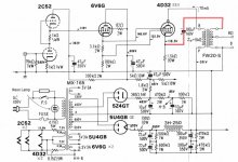
And the original schematic find, by AJT, of this similar configuration (likely from MJ magazine) is the 2nd schematic below, a 4D32 SE with CFB. Here, the 3.3K resister below the 6V6G follower is much more like what I've found for linearization of TV Sweep tubes. However, the 4D32 is a HV screen grid tube, with zero bias grid1. So I'm not absolutely sure how well it is performing in that design for linearization. It may actually want a higher value resistor there. But its in the ballpark for sure. I don't have one here to test on the tracer.
I should be able to get one of the 12G-B7 tubes to test cheaply though.
We would more likely use a Mosfet follower these days, but nothing wrong with a tube follower (except a floating heater).
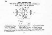
The oldest occurrence of this g2/g1 drive scheme appears to be this article in RCA Ham Tips:
"RCA-807's, used as zero-bias class B modulators, will furnish enough high-quality audio to fully modulate a quarter-kilowatt transmitter!"
http://n4trb.com/AmateurRadio/RCA_Ham_Tips/issues/rcahamtips0702.pdf
and see this thread where all this Crazyness started:
http://www.diyaudio.com/forums/tubes-valves/284614-screen-driven-6kd6-se-4.html#post4575031
and
http://www.diyaudio.com/forums/tubes-valves/284614-screen-driven-6kd6-se-3.html#post4572074
And its written up in the RCA transmitting tube manual too. But no where is there much comment on it for linearization use. TT4 manual from Pete's website. Bottom of page 239.
and another -almost- Crazy Drive schematic, except it appears to have a neg. bias on grid1
http://www.diyaudio.com/forums/tube...nificent-television-tubes-50.html#post4580952
And the original schematic find, by AJT, of this similar configuration (likely from MJ magazine) is the 2nd schematic below, a 4D32 SE with CFB. Here, the 3.3K resister below the 6V6G follower is much more like what I've found for linearization of TV Sweep tubes. However, the 4D32 is a HV screen grid tube, with zero bias grid1. So I'm not absolutely sure how well it is performing in that design for linearization. It may actually want a higher value resistor there. But its in the ballpark for sure. I don't have one here to test on the tracer.
I should be able to get one of the 12G-B7 tubes to test cheaply though.
We would more likely use a Mosfet follower these days, but nothing wrong with a tube follower (except a floating heater).
The oldest occurrence of this g2/g1 drive scheme appears to be this article in RCA Ham Tips:
"RCA-807's, used as zero-bias class B modulators, will furnish enough high-quality audio to fully modulate a quarter-kilowatt transmitter!"
http://n4trb.com/AmateurRadio/RCA_Ham_Tips/issues/rcahamtips0702.pdf
and see this thread where all this Crazyness started:
http://www.diyaudio.com/forums/tubes-valves/284614-screen-driven-6kd6-se-4.html#post4575031
and
http://www.diyaudio.com/forums/tubes-valves/284614-screen-driven-6kd6-se-3.html#post4572074
And its written up in the RCA transmitting tube manual too. But no where is there much comment on it for linearization use. TT4 manual from Pete's website. Bottom of page 239.
and another -almost- Crazy Drive schematic, except it appears to have a neg. bias on grid1
http://www.diyaudio.com/forums/tube...nificent-television-tubes-50.html#post4580952
Attachments
Last edited:
and a link to HOW it is linearizing the tube:
http://www.diyaudio.com/forums/tube...nificent-television-tubes-52.html#post4583046
and the RCA transmitting tube book "Special Triode Connection" TT4 (1956) page 239 below:
(notice they are using 20K Ohms for the R1 and R2 resistors, rather high for any linearization effect I think.)
The RCA Ham Tips article was from June 1947. So that's the earliest reference found so far. Could be something in RCA's reseach journal.... you would think we would have heard more about it then.
Attachments
Last edited:
- Home
- Amplifiers
- Tubes / Valves
- Those Magnificent Television Tubes