Thanks guys for the input. I went through quite a few schematics of different SS brand like Krell, Bryston, Aragon, Leach, Apex...........The only one that even have a clipping diode to avoid saturation is by Bonsai here. Nobody else even do anything and let it stick when clip.
There is no easy way to avoid clipping, I put in the diode just like Bonsai. I use the darlington VAS, so I just put the diode between the base and collector of the darlingtor to prevent the transistor from saturating. BUT the capacitance of the diode becomes part of the Miller feedback capacitance. The capacitance of the diode change with reverse particular when output getting close to the rail. So you do create a new problem when trying to solve another problem.
I looked at this Hiraga schematic. If you look at the top composite output transistor, the PNP U$5 can still saturate. So really how do you judge the clipping?
Last edited:
@camozzi:
Hi - I built a couple of Le Monstre amplifiers some years ago and I would suggest this:
- place some very HQ capacitors as close as possible to the actual amplifier circuitry
- omit the fuse when/if feasible - unless you have some good sounding types (thin copperwire may e.g. also be used - but like like a fuse it's an impedance in the PSU path)
- use a PCB with thick copper tracks. In my experience this is highly audible.
Just a few suggestions that came up ... ;-)
Cheers,
Jesper
Any advice, suggestion or recommendation is really welcome!
Hi - I built a couple of Le Monstre amplifiers some years ago and I would suggest this:
- place some very HQ capacitors as close as possible to the actual amplifier circuitry
- omit the fuse when/if feasible - unless you have some good sounding types (thin copperwire may e.g. also be used - but like like a fuse it's an impedance in the PSU path)
- use a PCB with thick copper tracks. In my experience this is highly audible.
Just a few suggestions that came up ... ;-)
Cheers,
Jesper
Hiraga "le monstre"
One more suggestion from my side. Don't use 9-0-9 secondary voltage for powering up. This is very less and will have ripple in power supply though it may measure 12V rectified voltage for DC. If possible try capacitance multiplier or some high current regulator along with large capacitance. It sounds very nice. Transformer could have 12-0-12V at least.
Sent from my iPad using Tapatalk
Hi! About your suggestions:@camozzi:
Hi - I built a couple of Le Monstre amplifiers some years ago and I would suggest this:
- place some very HQ capacitors as close as possible to the actual amplifier circuitry
- omit the fuse when/if feasible - unless you have some good sounding types (thin copperwire may e.g. also be used - but like like a fuse it's an impedance in the PSU path)
- use a PCB with thick copper tracks. In my experience this is highly audible.
Just a few suggestions that came up ... ;-)
Cheers,
Jesper
-When you talk about the HQ capacitors, do you talk about the capacitor mounted directly on the pcb? In that case, i opted for Panasonic os-con.
-About fuses, i know that sometimes, fuses could be like "bottle neck", and in effect, i never had problems with blowed fuses... but are the only protection inside the amplifier. Anyway, they are not used before the speaker, but before the pcb. Is there any other kind of protection that can be used here?
-About pcb thickness, i'm perfectly ok with you. The capacitor bank is mounted on a thick copper sheet and also the pcb that I bought from jims audio are very well builded (better than my expectations).
Thank you for your interest!
CIAO!
Thank you but I prefer the non regulated psu about sound, so 9-0-9 secondaries are mandatory if the psu is not regulated and you want to obtain 12V on the supply rails.
I did some test, but i remember that every time that i swap from regulated psu to a non regulated one, i preferred this last (IF A VERY LARGE AMOUNT OF CAPACITANCE IS USED). Maybe, i still haven't found a very good stabilized PSU for my case...
So, this is why i used trafos with 9-0-9 secondary.
Thank you for the interest!
CIAO!
@camozzi:
Hi ;-) .. A few more comments:
- for a "fuse" I would instead consider making a circuitry measuring the output voltage and if the voltage was above a certain DC level for some time (e.g. 10 seconds) it e.g. switches off a relay that connects the AC mains to the transformer. I reckon this can be done without any negative sound effects (basically a servo-opamp driving the relay).
- In my experience what really matters in order to achieve natural dynamics and detail is that a powerful PSU is placed close to the electronics. So, & this is said humbly!, if your PCB mounted capacitor is the one shown on the picture a few posts back then I would say that there could (easily) be something to gain with power supply. I personally would try to place capacitors closer to the output - as large as possible (while sounding "good" - whatever the preferences are here). Suggestions could be Nichicon KG (B grade) or KZ - but again preferences differ. Thick copper (2 mm wire for example) to the circuitry also is quite audible in my experience. A negative side-effect could, however, be parasitic oscillations ... FYI.
So, no further comments - good luck with your endeavors & listening 😉
Jesper
Hi ;-) .. A few more comments:
Hi! About your suggestions:
-When you talk about the HQ capacitors, do you talk about the capacitor mounted directly on the pcb? In that case, i opted for Panasonic os-con.
-About fuses, i know that sometimes, fuses could be like "bottle neck", and in effect, i never had problems with blowed fuses... but are the only protection inside the amplifier. Anyway, they are not used before the speaker, but before the pcb. Is there any other kind of protection that can be used here?
-About pcb thickness, i'm perfectly ok with you. The capacitor bank is mounted on a thick copper sheet and also the pcb that I bought from jims audio are very well builded (better than my expectations).
Thank you for your interest!
CIAO!
- for a "fuse" I would instead consider making a circuitry measuring the output voltage and if the voltage was above a certain DC level for some time (e.g. 10 seconds) it e.g. switches off a relay that connects the AC mains to the transformer. I reckon this can be done without any negative sound effects (basically a servo-opamp driving the relay).
- In my experience what really matters in order to achieve natural dynamics and detail is that a powerful PSU is placed close to the electronics. So, & this is said humbly!, if your PCB mounted capacitor is the one shown on the picture a few posts back then I would say that there could (easily) be something to gain with power supply. I personally would try to place capacitors closer to the output - as large as possible (while sounding "good" - whatever the preferences are here). Suggestions could be Nichicon KG (B grade) or KZ - but again preferences differ. Thick copper (2 mm wire for example) to the circuitry also is quite audible in my experience. A negative side-effect could, however, be parasitic oscillations ... FYI.
So, no further comments - good luck with your endeavors & listening 😉
Jesper
-Yes, probably the circuitry that control the relay is the best thing about protection without sound degradation... but if you see the remaining space in my cabinet... Anyway is a really interesting thing! Can you show a schematic to do this???
-About the possibilities to place capacitors close to the pcb, they are divided only from 5 centimetres of litz wire (and fuses in the middle)... So , how I can put the capacitor closer to pcb?
CIAO!
-About the possibilities to place capacitors close to the pcb, they are divided only from 5 centimetres of litz wire (and fuses in the middle)... So , how I can put the capacitor closer to pcb?
CIAO!
Hi again ...
No, I can't really ... I'll have to take some time to think about it and I don't have the energy for this right now.
However, please remember this:
When tracks are shortened so is the inductance which - all else equal - may lead to a higher bandwidth potentially causing oscillations ... I say this because although in my experience placing capacitors immediately next to a circuitry may make for a quite different amplifier one also needs to know what one is doing ... And how to amend potential damage/oscillations ...
Best regards,
Jesper
Can you show a schematic to do this???
No, I can't really ... I'll have to take some time to think about it and I don't have the energy for this right now.
If this is interesting to you I suggest you are creative - to my eyes there would be many possibilities to place the (mentioned) capacitors closer to the circuitry ...-About the possibilities to place capacitors close to the pcb, they are divided only from 5 centimetres of litz wire (and fuses in the middle)... So , how I can put the capacitor closer to pcb?
However, please remember this:
A negative side-effect could, however, be parasitic oscillations ... FYI.
When tracks are shortened so is the inductance which - all else equal - may lead to a higher bandwidth potentially causing oscillations ... I say this because although in my experience placing capacitors immediately next to a circuitry may make for a quite different amplifier one also needs to know what one is doing ... And how to amend potential damage/oscillations ...
Best regards,
Jesper
Its not clear if you are planning 1.1F for single rail or total channel.
Also battery is good option though I prefer its bulky. I could get absolute silence and thick voice using 33000uF smoothing capacitor followed by capacitance multiplier and before amplifier another 2x33000uF. All this for single rail.
Sent from my E6 using Tapatalk
Also battery is good option though I prefer its bulky. I could get absolute silence and thick voice using 33000uF smoothing capacitor followed by capacitance multiplier and before amplifier another 2x33000uF. All this for single rail.
Sent from my E6 using Tapatalk
Ha-ha - trimmer in FB.., about other I don't have words.😀😀😀😀 You're hard man.😀
Better to make original scheme or not to make at all.🙂
Better to make original scheme or not to make at all.🙂
Hi guys,
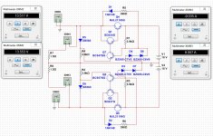
I can't get close to 0mv, so I tried a DC servo, any suggestions?
BTW, I use SANKEN 2SC2922/2SA1216 as output driver, as the schematic.
Any modifications needed?
THD is around 1% and output is 3W, not very satisfied.
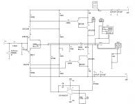
A DC servo should work nicely in this application. I haven't used one but I did with my JHL10 build and it works perfectly. I think the issue with your implementation is that it doesn't have any ground reference to seek. As it is all it is doing is smoothing the DC bias.
Look at this implementation from Tubecad for an idea of how to reference it to ground:
Shoog
Attachments

Hi damon1983,
how do you deal with DC offset? by transistor matching or?
🙂
Hi, I didn't have any problems with DC out (it was approx +-2..5 mV) and bias. In final I'd made Hiraga's Class A 20W (1980).
If you don't have 2SK170+2SJ74, that better to make another amplifier.🙂
Hi guys,
I can't get close to 0mv, so I tried a DC servo, any suggestions?
THD is around 1% and output is 3W, not very satisfied.
Try to reduce R6 to 470 ohms, or 330 ohms.
Jfets are not so complementary after all, and ususally they skew into the N-channel path.
You could also try and place a 100 ohms between the N-channel source and the trimmer ( or increase the trimmer value to 200 ohms).
Edit: The trimmer I am talking about is the one called "65%" used as source degenerators.
Last edited:
Ha! I do have some genuine 170/74, and my budget is limited(higher power means larger transformer and money), I planed to use it driving a bookshelf speaker, so 10W might be just good.
But yes, Hiraga's 20W is also one of my choices. Thanks a lot!
But yes, Hiraga's 20W is also one of my choices. Thanks a lot!
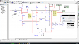
Correction:
DC offset =~ 405uV ! under this config
About 10X improvement.
Thank you Shoog!
DC offset =~ 405uV ! under this config
About 10X improvement.
Thank you Shoog!
Attachments
Last edited:
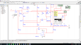
Try injecting the DC servo in place of the bias adjustment pot at point A. You should be able to replace the pot with a pair of fixed resistors.
Once you have this setup you need to implement a DC speaker protection circuit to protect against failure of the DC servo.
Shoog
Once you have this setup you need to implement a DC speaker protection circuit to protect against failure of the DC servo.
Shoog
- Home
- Amplifiers
- Solid State
- Hiraga "Le Monstre"