here i made a small one 200 mm high, i had no idea how thick the copper tape was i used to resistance ended up being 1.2 ohm 🙂 hehe
it is8 db more efficient then my quads so thats good 🙂
distortion is on the right track to be honest i just used normal 80grams print paper and PVC closed foam to dampen just a bunch of strips on the paper to damp.
i did use a low shelf because high frequency is still a problem, so from 600 - 7Khz is even 8db lower now then it would without eq to compensate for high frequency rolloff.
and a high shelf +5 dB from 16khz and up
measured at 30 cm distrance
crossed at 700
Attachments

oh made one mistake 🙂 the settings on the bass channel where still for the ob driver 🙂 haha. so they match pretty nice, only 600 to 7000hz are shelved down with 8dB and + 4 at 16khz high shelf. there is nothing in the gain department changed both at 0. would ncie if there was a way to increase that high end isntead of decreasing the rest 🙁
then if it where a 4 ohm version you would eb around 88db efficiency with cheap magnets, 40x20x5 🙂
then if it where a 4 ohm version you would eb around 88db efficiency with cheap magnets, 40x20x5 🙂
well rubanoid is a weird thing the physical contrustion wont allow for good HF. its retarded that they sell for so much money.
as i expected where the cylinders meet there are isues with HF, now i damped one side and it is apparant, that when the mic faces the non damped side HF is extended. in the midlle its crap and facing the damped side is terible 🙂
this cavity is its downfall. removing another cylinder would solve it i guess 🙂but low end will suffer. and you end up with the wing speaker design 🙂 i think
well rubanoid is a weird thing the physical contrustion wont allow for good HF. its retarded that they sell for so much money.
as i expected where the cylinders meet there are isues with HF, now i damped one side and it is apparant, that when the mic faces the non damped side HF is extended. in the midlle its crap and facing the damped side is terible 🙂
this cavity is its downfall. removing another cylinder would solve it i guess 🙂but low end will suffer. and you end up with the wing speaker design 🙂 i think
Hi Wrine,
Interesting findings youve got here. I think that you forgotten what sayed the guy from Lineaum: you have to reduce the center of the coils mass to improve high frecvency response. Then you have to deflect the sound thats coming from here also. I think that some V shaped placed on the top and bottom of the speaker would be fine and a curved one would be even better.
A guy that has developed the ruban to a point for Audio Consulting said that deflecting the top and the bottom did improved the hights, also deflecting the lateralls at the same time with the top and bottom improved the 3d effect of these speakers and gave a bit more focused sound. He also sayed that a dense whool dampening that is 3cm thick and the lenght of the cylinder placed insyde the cylinders between the magnets and the laterall vertical rods reduces the resonance dramatically. Also some thin dampening tape sticked on the magnet plates inside the cilinders lowered the nasty reflected resonances. He sayed that stufening all the cilinder with whool or any other dampening material
has worsened the frecvency response.
Im planning for purchasing a printer at the end of this year. Who knows maybe Santa will bring it to me for free. 😀 I have to talk to my Santa wyfe for this.. Hehehe... 🙂
Thanks for the sugestions my friend. I cant wait to test these speakers.
Cheers
Sergiu
here i made a small one 200 mm high, i had no idea how thick the copper tape was i used to resistance ended up being 1.2 ohm 🙂 hehe
it is8 db more efficient then my quads so thats good 🙂
distortion is on the right track to be honest i just used normal 80grams print paper and PVC closed foam to dampen just a bunch of strips on the paper to damp.
i did use a low shelf because high frequency is still a problem, so from 600 - 7Khz is even 8db lower now then it would without eq to compensate for high frequency rolloff.
and a high shelf +5 dB from 16khz and up
measured at 30 cm distrance
crossed at 700
Very promicing results my friend.
Cheers
Sergiu
Hi Wrine,
Interesting findings youve got here. I think that you forgotten what sayed the guy from Lineaum: you have to reduce the center of the coils mass to improve high frecvency response. Then you have to deflect the sound thats coming from here also. I think that some V shaped placed on the top and bottom of the speaker would be fine and a curved one would be even better.
A guy that has developed the ruban to a point for Audio Consulting said that deflecting the top and the bottom did improved the hights, also deflecting the lateralls at the same time with the top and bottom improved the 3d effect of these speakers and gave a bit more focused sound. He also sayed that a dense whool dampening that is 3cm thick and the lenght of the cylinder placed insyde the cylinders between the magnets and the laterall vertical rods reduces the resonance dramatically. Also some thin dampening tape sticked on the magnet plates inside the cilinders lowered the nasty reflected resonances. He sayed that stufening all the cilinder with whool or any other dampening material
has worsened the frecvency response.
Im planning for purchasing a printer at the end of this year. Who knows maybe Santa will bring it to me for free. 😀 I have to talk to my Santa wyfe for this.. Hehehe... 🙂
Thanks for the sugestions my friend. I cant wait to test these speakers.
Cheers
Sergiu
well you might be very positive to be honest. my thoughts about this are these
1. reducing center mass, my coil is on 0.100 micron polyester glued on 2 pieces of 80 grams of paper. as far as i know no one used this light paper and i cant believe they made the coil lighter, since its already hard to keep it flat. ive seen rubanoides with epoxy and thick paper , also in this thread, as the way to go but this would not work with the theory that i have to remove 0.2 grams of paper of the inside of the coil. believe me i tried... it does not work at all.
2. the wings they use looks more like a normal baffle to extend low frequency, since all high fequency is emited from the center. the 2 pieces of wood dont do much for these frequencys .
3. all measurements i've seen so far have a huge peak in 11Khz or such and a huge drop near 15khz. its not the material since use thinner stuff then Henjo, for instance . but his measurement look pretty much the same. so its not a function of weight its something else.
in my former jpg it looks flat but only after haevy EQ and only on axis. of axis all starts to crumble.
am sure it can be better , but there are some limitations to this system, and what i've seen now in the commercial products dont address these faults at all.
our job to make it better and dont be afraid of measurements 🙂 the high ends scene in rubanoids seem to be at least. since there graphs will look as awfull as ours. thats no way of asking 10000 for a speaker when you data looks like alps. but some how they do 🙂
i must admit that even when it measures bad it sounds appealing , it does somehow has the ability to sound good even if it does not measure well.
but still i rather have some data to back it up. and as you know there is not even one measurement of the speakers you talk about 🙁 nore the orignal janus nore the high end version with the wood crap
Last edited:
Ok die Some measurements with 1/4 of the cuykinders normally present in a rubanoide .
It interesting, since you can see more clearly what happens with the high frequenxys emiting from the
It interesting, since you can see more clearly what happens with the high frequenxys emiting from the
Ok die Some measurements with 1/4 of the cuykinders normally present in a rubanoide .
It interesting, since you can see more clearly what happens with the high frequenxys emiting from the
What happended here my friend?
off: Merry Chrystmas to everyone here and to all our colleagues that are watching this thread and are contribuiting directly and indirectly on this thread and our comunity.
Cheers
Sergiu
Cheers
Sergiu
Whoops my phone posted that without my permission 🙂 I wanted to say now no time to do any more tests because of christmass although I would love to Fidl around right now !!!
And I wanted to say merry christmass to all.
I will post my observations later 🙂 dont eat to much !!!!
And I wanted to say merry christmass to all.
I will post my observations later 🙂 dont eat to much !!!!
Hi Wrine,
I'm planning to buy a printer but the problem is how do i make it to print a 55cm coil?
Your coil is smaller but mine...
Do you know any program or sollution for this problem?
I have googled this issue but couldnt find anything on the net..
Thanks in advance.
Sergiu
PS: Happy birthaday to everyone!
I'm planning to buy a printer but the problem is how do i make it to print a 55cm coil?
Your coil is smaller but mine...
Do you know any program or sollution for this problem?
I have googled this issue but couldnt find anything on the net..
Thanks in advance.
Sergiu
PS: Happy birthaday to everyone!
Hi sergiu2009
i did not see you comment. well yeah printing is limited to 30 cm as far as i know. 🙁 i printed 2 coils yesterday since i looked back to some old posts of mine witch had pretty decent results in the end. compared to esl's and other forms of producing sound 🙂
i am trying to replicate it but my lack of documentation lead me to experiment again 🙂 i got one playing now but the high freq cuts of at 13 khz, even when used 120 grams paper..... i used to much glue i guess, and i used 2 x 0.1mm Polyester foil to print the coils on. i need my nomex since i got to 14khz nomex with 0.25mm . i did ask for some samples of nomex in the range of 0.08 to 0.18 mm
if nomex is used i can add copper tape directly to the nomex without using a laminate. then print it so i lose the stuff in between. nomex is water resistant, so it can be etched. i am not yet out of the coil construction. using 2x4 Ohm or using 1x 4 Ohm, 4 Ohm is lighter. but power handling is less. for me the gluen is also an isue, i used PU glue last time and it becomes very nice flat solid . but PU tends to be soaky (rubbery) and foams so this might cripple the HF. my experience is that the coil carrier needs to be as light and solid as possible.
i might try a sort of epoxy, but usually the time to dry is to long for me 🙂
the rest of the freq range from 900 hz to 14 kHz looked pretty good.(almost as good as some esl,amt's i measured, from own making that is)
although the HF extends is not as high as i would like this was the most solid and easy to install membrane i ever made, just adjust some strings top and bottom and it is ready to play, i did not even used the damping from foam tape yet so there is much to gain in the distortion department around 300-800 Hz.
efficiency is pretty good, not the insane 100 dB mentioned, since i use shitty magnets half the size. but still pretty good. i can imagine using thinner metal, with a smaller panel to increasy flux. since i want to use it 300-400Hz and up it does not need 8mm of Xmax :0 rather 1mm MAX. ofc at 1mm the metal will be saturated, but i will model some metal tomorrow for lets say 4mm, if we can manage to get a stable coild then you can decrease gap as well, increasing efficiency even more. aaaaaah well so many options. as usual 🙂
Hi Sergui,
As expected it has hardly no influence.
Here is what I simulated.
View attachment 492173
Henjo
some late reply. but i was thinking about the same... it does mater but you model ism not correct. what he does is limit the flux to the piece of steel that is outside the gap. by slitting the metal the piece that is left will go to the max field strength possible for this material. so above this slit there will be around 0.1-0.15 tesla less. so its not working wonders but still . i modeled it on a gap stretch of 0.5 tesla so still a decent percentage, of magnet force NOT goin where it should not belong. this is also the perfect spot to have the horizontal coil leads, if you want to make it as perfect as possible.
excuse me for the late reply, im rereading the thread to see if i missed something usefull in the progress.
Silhouette Portrait or Camaro is able to draw as well as cut.
If you make a long cutting mat and put the length in the settings you are able to draw a long 20cm or 30cm. drawing with the pencil you choose.
Length is more than 100cm.
Bernt
If you make a long cutting mat and put the length in the settings you are able to draw a long 20cm or 30cm. drawing with the pencil you choose.
Length is more than 100cm.
Bernt
Silhouette Portrait or Camaro is able to draw as well as cut.
If you make a long cutting mat and put the length in the settings you are able to draw a long 20cm or 30cm. drawing with the pencil you choose.
Length is more than 100cm.
Bernt
well for a amt the Silhouette outperforms my way of making a coil since you are able to make a very big one(also choices in lamination are bigger). but for the rubanoide i am not sure. it depends on the spacing it can handle. can a cameo cut 0.3 mm traces in between? since you want to force as many traces into a small space to be able to have some power handling and the needed resistance,
what do you mean by draw? by using a etch resist marker? as a plotter?
would still love to add a Silhouette to my arsenal 🙂 it is a very nice tool for all sorts of things including making some awesome amt's
also cutting the membrane for a rubanoide with slits and holes and such. you could make some verry complicated forms... damned should not have bought so much conductive mesh for 130 euro but a second hand Silhouette 🙂
Last edited:
Yes it can work as a plotter.
I can make a test with 0.5mm traces and 1mm coil.
Could you make the coil with 2 or more layer.
Bernt
I can make a test with 0.5mm traces and 1mm coil.
Could you make the coil with 2 or more layer.
Bernt
Wel i can make any width of conductor but the resolution in between traces is 0,20 - 0,3 mm max. I could stack coils as long as there is something in between the coils to separate them from each other or to stick my Alu or copper to.
So I use polyester 0,1 mm stick copper tape to it , print traces , etch it and stick it to the membrane. Might be able to use thinner backing for the coil of course . Or if the membrane material is water resistant I can stick the conducting tape of choice directly witch saves weight. Hence why I want some nomex samples
So I use polyester 0,1 mm stick copper tape to it , print traces , etch it and stick it to the membrane. Might be able to use thinner backing for the coil of course . Or if the membrane material is water resistant I can stick the conducting tape of choice directly witch saves weight. Hence why I want some nomex samples
i couldn't help myself...
thankyou so much for this thread, especially wrine....
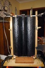
after all your valiant efforts with rubanoids, i was inspired and decided to try a rubanoid spin-off of my own design. due to my twisted style, love of difficult things, and general stupidity, i am attempting to use three lobes, the theory being that the middle one is pistonic. so, you ask? well, ok, 3 is my favourite number....
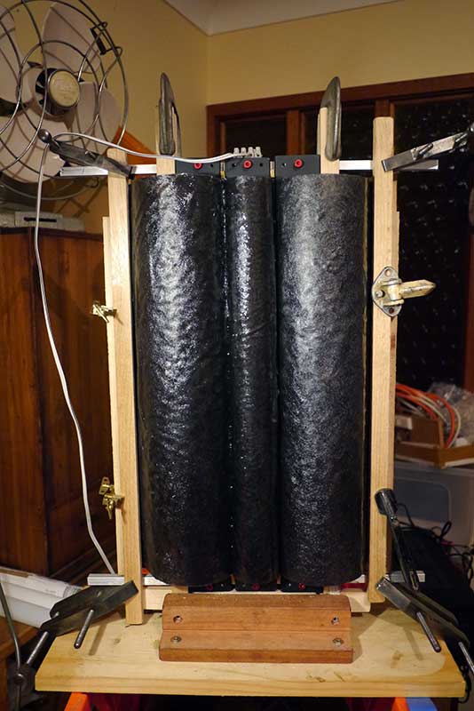
this first test one works well. it makes music. 😀 amazing. the fun and wonder of making my own speaker, not just building some boxes for store-bought drivers like usual, is pretty great!
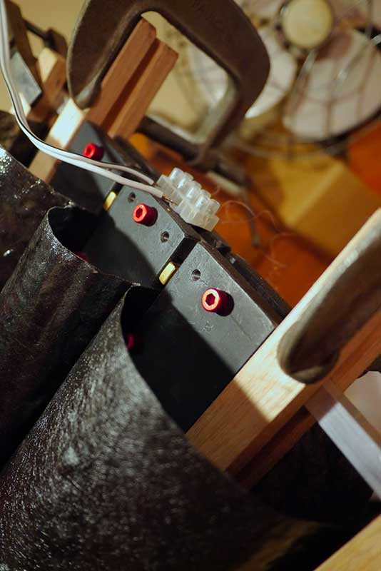
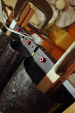
450mm long membranes in carbon fibre and epoxy. N52 magnets - too many for someone who has not much money. hand wound 0.2mm copper wire coils - 33 winds - 16 ohms per side wired in parallel for 8ohm nominal. here is a vimeo video of it playing....
i have two questions as i go further:
next up in this project is making the magnet assembly for the other side, proper measurement, lighter membranes (silk or paper doped, with the coils set in epoxy between the lobes), sourcing copper braided wire for connections to the membrane, and a new system of hanging/tracking to keep it all perfectly in the air gap. surprisingly, i removed my dodgy noisy trial tracking setup because it was not needed - the membrane stays pretty well in the gap once aligned on the sides....until some heavy bass, when it starts to go out of shape and move like a jellyfish....
my initial thoughts on these working prototypes:
thanks to all of those who posted on this - i was inspired, and am now having fun mucking about with possibilities and learning heaps along the way. great stuff! will post a proper build thread when i get a little more done.
thankyou so much for this thread, especially wrine....
after all your valiant efforts with rubanoids, i was inspired and decided to try a rubanoid spin-off of my own design. due to my twisted style, love of difficult things, and general stupidity, i am attempting to use three lobes, the theory being that the middle one is pistonic. so, you ask? well, ok, 3 is my favourite number....
this first test one works well. it makes music. 😀 amazing. the fun and wonder of making my own speaker, not just building some boxes for store-bought drivers like usual, is pretty great!
450mm long membranes in carbon fibre and epoxy. N52 magnets - too many for someone who has not much money. hand wound 0.2mm copper wire coils - 33 winds - 16 ohms per side wired in parallel for 8ohm nominal. here is a vimeo video of it playing....
i have two questions as i go further:
- has anyone found any good sources of info regarding membranes, resonances in them, and how to dampen it all, and generally understand what is going on in the vibrating surface?
- where is some good info on measurement of speakers with inexpensive equipment?
next up in this project is making the magnet assembly for the other side, proper measurement, lighter membranes (silk or paper doped, with the coils set in epoxy between the lobes), sourcing copper braided wire for connections to the membrane, and a new system of hanging/tracking to keep it all perfectly in the air gap. surprisingly, i removed my dodgy noisy trial tracking setup because it was not needed - the membrane stays pretty well in the gap once aligned on the sides....until some heavy bass, when it starts to go out of shape and move like a jellyfish....
my initial thoughts on these working prototypes:
- my membrane is carbon fibre with epoxy set over a three-part mould - too heavy. i am thinking of trying doped silk and paper as well. yet the carbon fibre still gets clearly to 13khz with this weight, but drops dead at higher frequencies (or my ears do....)
- they are also very directional at higher frequencies, not so much horizontally (though there is definitely a sweet spot), but vertically - they need to be placed at the right height....
- they have some ringing on certain notes, evident in high pitches of piano and xylophone - certain percussive high tones really can be harsh. need to track down those resonances and trial damping methods in places....
- the bass is very nice - especially drums - they sound like real drums! i would like to chase this bass side of them a little, maybe through a trial with an upsized wave guide (at this size i guess that would make them more like sculpted O.B.'s...?!)
- its all untested as to efficiency or any other hard numbers....
- they are a ridiculous pain to make, especially the composite membranes, and the coils, and the magnet assembly (having three plates makes for more fun and danger....), and the final tweaking to get rid of rattles and hums, not to mention finding bad resonances yet....
thanks to all of those who posted on this - i was inspired, and am now having fun mucking about with possibilities and learning heaps along the way. great stuff! will post a proper build thread when i get a little more done.
Attachments
Congrats orangelplaca,
Very well done. My ruban is still waiting in Romania... i'm now in Deutchland to work and make some more money but will be home in three months to start testing again. Some of my thoughts are:
*your magnets STAS n52 is perfect;
* the membrane is too heavy;
* you should cease to make hand winded coils as they wont go upper than 14khz. Francois Deminiere ( the producer of Janus 50 speaker ) admits this on his webpage, and says that printed coils goes up to about 20khz. That is why I asked Wrine about 50cm printed coils.. I dont know how to print them except that I should place an order on a pcb maker for this aspect...
I am happy that others are encouraged and motivated to do this speaker. I cant wait to begin the tests again.
Ps: Audio Consulting has sone kind of whashi paper ( old receipt from Japan)at about 200gr and sais that is working without problems.
I think I will go to the carnaval today in Aachen. Anyone here lives there or is allready there?
Cheers
Sergiu
- Home
- Loudspeakers
- Planars & Exotics
- A DIY Ribbon Speaker of a different Kind