For a drawing begginer like, which drawing program could be interesting and easy to use to make speaker's enclosure plan?
As keeping the same front panel as the petite Onken, I'm thinking to place the woofer at the same place as the 414. This said, I read that Koïzumi have done more than 80 different tries on its position!!! I'm wondering if there is serious thing to consider regarding this placement.
No clue, but would like to know also.
Yes, there's mathematically ideal locations and for a typical golden ratio cab, it's ideal offset is around 0.42 IIRC. As the vented cab's aspect ratio increases there comes a point where it develops 1/4 WL TL pipe action that increases damping on the vent if down near/at the bottom, so in this situation the driver's ideal location becomes a function of its length, cross sectional area and taper ratio, if any based on how smooth a response one wants, i.e. how much internal damping is required to smooth it out.
In general, both the driver and vent will be at the pipe's odd harmonics, though simple math division by an odd number isn't accurate; such as for a simple straight taper, 1/3 [0.333] down is actually at 0.349-0.3553 [depending on who you 'ask'] in theory, but I've learned that this is just an average of sorts since it doesn't take other factors into account, though plenty close enough, so no need to 'sweat the small stuff' as even 0.33-0.4 only means slightly different stuffing densities, i.e. only important if trying to eek out the speaker's max acoustical gain for prosound or 'flea power' amps apps.
Olson's work on this is as relevant today as it was 60+ years ago [actually it was in his 'late '30s book IIRC], so for a little bit more in-depth tutorial [Chapter III]: http://cyrille.pinton.free.fr/electroac/lectures_utiles/son/Olson.pdf
Anyway, MJK has documented the 'good enough' driver offsets of various pipe tapers: http://www.quarter-wave.com/TLs/Alignment_Tables.pdf
GM
For sure, I'd like to keep the cleat of 25mm x 25mm situated just below the woofer (see picture above). But my question is more oriented on the lateral bracing of the enclosure. I'm wondering if a good idea would be to have a second 25mm x 25mm cleat in this axis. What do you guys think?
The goals are to keep the cab from 'breathing' and to provide the driver with a sufficiently rigid/damped work 'platform' to maximize its electro-mechanical, acoustical efficiency; so yes, all six sides need to be tied together and the driver braced/mass loaded to it.
Look at Dave p10's bracing schemes for what I mean, though all that hole drilling is way too much for me, so I just use closet rod or 2x2 or 1x3 boards, etc., scrap [including chain link fence rail or similar] tied together, then wrapped with fiberglass insulation. All that fancy internal woodworking that's not normally seen is wasted on me, I got better things to do, but do envy their seemingly boundless patience.
GM
Hi GM,
I read the article regarding damping factor. I am able to understand the idea behind the influence of the damping factor on speakers. But the other texts you suggested me are far away of my comprehension. It touches one of my concern about speaker's design. I'm not a speaker deisgner. That was my main concern while considering a "new" classic design of bass-reflex for a GPA 416-8B speaker.
When André came with its simple idea and plan, it motivated me, but I quickly reach my limit when we enter these complexe informations. Anyway, I try to do the best I can to understand them.
Have a good day,
Sébastien
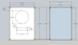
OK, then based on your planned cab and assuming it will have the same baffle dimensions as shown in the article, then I recommend mounting the driver down 336 mm rather than its 280 mm.
GM
GM
Excellent! Thank you GM. I'll soon begin the drawing of what could be a preliminary plan of the cab.
Sébastien
Sébastien

Hi everyone,
André is of great help. We are doing some adjustments from this option but I think that we are pretty close from something classical and interesting for me.
GM, I draw the option you had suggested above. See attached picture.
This said, I prefer André's proportion which put the speaker higher on the baffle. I looks more natural and has André told me, we are keeping emissive source even closer one to another.
Sébastien
Attachments
I thought you were building a deeper Petite Onken for the 416, not a simple reflex, so while ~0.42 IIRC is the theoretical ideal, there's little difference where it is along the baffle and to the first approximation, minimizing the CTC spacing is a good plan.
That said, when a long horn is one of them there's the matter of how the mounting distance, tilt of it combined with the XO's time/phase offset determines how well the two sum at the LP, oftimes making a short CTC spacing a bad plan: Linkwitz-Riley Crossovers: A Primer
GM
That said, when a long horn is one of them there's the matter of how the mounting distance, tilt of it combined with the XO's time/phase offset determines how well the two sum at the LP, oftimes making a short CTC spacing a bad plan: Linkwitz-Riley Crossovers: A Primer
GM
Hi GM,
About the center to center (CTC), which part of the speaker you are talking about? Is it for example from the center of the woofer vs. the center of the mid-driver? And precisely on its emissive source. Which could be in the drive for such compression.
Regarding time alignment, a subject on which I worked a bit in the last year, I don't understand why you mean that it's worst if emissive sources are closer.
Sébastien
Curious why the cabs appear to be upside down and how you get good integration at the LP with such a wide driver CTC spacing.
GM
It's an excellent question, partially because my father in law added bases that I had not planned on, and because originally I had planned to integrate the mids and highs into the cabinet so there was room for them. Given the later changes that occurred they would not fit. It does bother me, but no fix is in the offing, and as I have shifted the XO points lower over time it becomes less and less of an issue.
I am now crossing at 680Hz which helps with the acoustical center to center issues.
The fact that it works as well as it does might be serendipity. I've measured extensively and I don't think anyone could tell from looking at the graphs where I cross from the woofers to the midrange drivers. I can't hear or measure any obvious deficits either due to the wide CTC. I may be getting away with it because the mids and HF drivers aren't point sources and aren't integrating near the baffle which is obvious during measurement, however at the listening position they are fully integrated. XO are all 2nd order LR, and I do use some mild parametric room EQ, no more than a couple of dB of boost or cut is required. Measured response from 200Hz - 20kHz falls comfortably inside of +/-2dB. Room interactions below 200Hz make LF measurement difficult but oddly the system does not start its steep dive into oblivion until 28Hz. (Below 35Hz most of the radiation is from the ports) The room is cluttered but strangely enough is the best sounding room I have ever had, not a lot of obvious artifacts. I'll give Jim Smith and his book some credit.
Hi GM,
About the center to center (CTC), which part of the speaker you are talking about? Is it for example from the center of the woofer vs. the center of the mid-driver? And precisely on its emissive source. Which could be in the drive for such compression.
Regarding time alignment, a subject on which I worked a bit in the last year, I don't understand why you mean that it's worst if emissive sources are closer.
Sébastien
Greets!
AKAIK, CTC only is used to define the center-line distance between two drivers.
If the Rane paper doesn't make it clear to you, then I don't know how to do better without putting a lot more time into it than I'm willing to 'afford', sorry.
Don't what you mean by 'Which could be in the drive for such compression.'
GM
It's an excellent question....
Cool! Whatever works! 'Cluttered' is good as it makes for a diffuse sound-field.
FWIW, my 'litmus test' was a long unavailable CBS test record for this and later switched to Johnny Winter Group's 'Frankenstein', again, only on vinyl. No clue about other recordings.
If the music remains vertically stable throughout, then there's good summation at the LP, but to date the only speakers that I know can do it at typical room distances are 'FR' drivers, some co-axes and Unity/Synergy horns.
GM
Greets!
AKAIK, CTC only is used to define the center-line distance between two drivers.
If the Rane paper doesn't make it clear to you, then I don't know how to do better without putting a lot more time into it than I'm willing to 'afford', sorry.
Don't what you mean by 'Which could be in the drive for such compression.'
GM
GM,
I read back the sentence above "Which could be in the drive for such compression." and I don't even understand what I was talking about. 🙂 I think I lost an idea because I remember correcting this post and had to go, went back and sent it. Anyway, we have to forget this one.
I'm accustomed a bit to the content of Rane's paper from some reading and discussion made in the last few years. I think that I figure well the time alignment problematic and how to resolve it. But it won't be perfectly aligned easily with such a design. It would be a lot easier with bass horn to set every emissive sources on the beginning of its initial impulsion. This is quite easy to do with REW.
This said, I don't exactly figure what would be the big difference with a woofer 10 cm higher or lowered concerning directivities lobes. But maybe I still miss something.
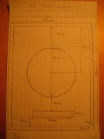
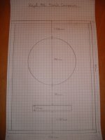
Finally, here's a plan for the bass-reflex cab to come which I really like. In the end, it is between your first suggestion and André's one. This gives a classic look with right proportions to my eyes.
Sébastien
Attachments
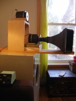
To illustrate my purpose about the difficulty of time alignment with such a design, here's a picture I took last year while doing a test with perfectly align 3 ways on the beginning of impulsion using REW.
Not so WAF and kids friendly... 🙄
Sébastien
Not so WAF and kids friendly... 🙄
Sébastien
Attachments
http://www.diyaudio.com/forums/atta...734-beyond-petite-onken-projet-416-face-2.jpg
Looks like one of Altec-Lansing's longest 'running' 15" cab designs, the 620, which dates from before WWII as a Lansing Manufacturing utility cab. 😉
Late vertical vent + front tone controls cutout variation shown: http://www.lansingheritage.org/images/altec/plans/1970's-lf-plans/enclosures07.jpg
GM
Looks like one of Altec-Lansing's longest 'running' 15" cab designs, the 620, which dates from before WWII as a Lansing Manufacturing utility cab. 😉
Late vertical vent + front tone controls cutout variation shown: http://www.lansingheritage.org/images/altec/plans/1970's-lf-plans/enclosures07.jpg
GM
Last edited:
To illustrate my purpose about the difficulty of time alignment ......
Yes, if you don't account for it in the XO, one of the points in the Rane doc.
GM
Good morning GM,
Thanks for the link, I don't know this Altec cab, but we are aware that we are not creating any new here. It's really a classic design and the example from 620 proves it.
I don't think of an important influence from the cross-over in my set-up. I use a Kaneda inspired cross-over at 6 dB/oct. on each speaker. With other cross-over, I know it could be way more complicated.
Have a good day,
Sébastien
...Looks like one of Altec-Lansing's longest 'running' 15" cab designs, the 620, which dates from before WWII as a Lansing Manufacturing utility cab. 😉
Late vertical vent + front tone controls cutout variation shown: http://www.lansingheritage.org/images/altec/plans/1970's-lf-plans/enclosures07.jpg
GM
Thanks for the link, I don't know this Altec cab, but we are aware that we are not creating any new here. It's really a classic design and the example from 620 proves it.
Yes, if you don't account for it in the XO, one of the points in the Rane doc.
GM
I don't think of an important influence from the cross-over in my set-up. I use a Kaneda inspired cross-over at 6 dB/oct. on each speaker. With other cross-over, I know it could be way more complicated.
Have a good day,
Sébastien
To illustrate my purpose about the difficulty of time alignment with such a design, here's a picture I took last year while doing a test with perfectly align 3 ways on the beginning of impulsion using REW.
Not so WAF and kids friendly... 🙄
Sébastien
Hmm, my system ended up pretty much the same way.. LOL
Yes, if you don't account for it in the XO, one of the points in the Rane doc.
GM
Very difficult to do passively I think, easy in DSP.. I do it with physical driver offsets, I'm not a good enough XO designer to do anything cleverer than Butterworth or LR. It sort of works, impulse response is recognizable but not great, the XO are second order with what that implies for phase response through the crossover region. Behavior in the FR domain is quite good. Efficiency concerns and limited available power incline me to make things no more complex than required.
- Home
- Loudspeakers
- Multi-Way
- Beyond the petite Onken