...and here is the simulation of a 50W amp (non-Miller) at 20kHz and 30kHz. The difference between the input and output signal is a time delay. The powerpoint arrow is the same length for both signals and shows 230 nS. I call this a delay, not a phase shift, as a phase shift is usually taken to vary with frequency (as per RC time constant).
Attachments
...and here is the simulation of a 50W amp (non-Miller) at 20kHz and 30kHz. The difference between the input and output signal is a time delay. The powerpoint arrow is the same length for both signals and shows 230 nS. I call this a delay, not a phase shift, as a phase shift is usually taken to vary with frequency (as per RC time constant).
Can you show how did you simulate this? I don't believe this is correct.
It is correct Damir, the delay is the same, at least in the áudio band.
Sergio, not in my simulation. I compare + input with - input(feedback) signals. How you call that time delay? Propagation delay could be the same in the audio band, but how do you simulate it?
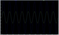
Here are my results... 1 KHz and 30 KHz.
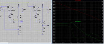
Vas current in red, note the 90 degrees phase-shift on the current, the same 90 degrees you find in the loop gain of this circuit.
And the input and Feedback are spot on the same.
I have reduced Gain to app 6 DB in order to make a more illustrative plots where the apex's are clear.
Vas current in red, note the 90 degrees phase-shift on the current, the same 90 degrees you find in the loop gain of this circuit.
And the input and Feedback are spot on the same.
I have reduced Gain to app 6 DB in order to make a more illustrative plots where the apex's are clear.
Attachments

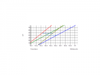
You have to make sure the DC is zero in the IN+ and IN- , I have -360.594uV of DC in the IN- so I compensate that by enter this ( V(in-)+360.594u ) in the plot, like in the first image. And then I measure the diference in time ( at the cross of zero ) between IN+ and IN- .
The delay of the simple miller and the TMC Amplifiers resemble the delay you have with a simple RC filter like this one in second picture.
In my amp I have 208nS at 10Hz, 2Khz, 20Khz, at 100Khz I have 207.5nS at 330Khz it is 201nS.
The delay of the simple miller and the TMC Amplifiers resemble the delay you have with a simple RC filter like this one in second picture.
In my amp I have 208nS at 10Hz, 2Khz, 20Khz, at 100Khz I have 207.5nS at 330Khz it is 201nS.
Attachments
Jan can you make me the favor of reading the post #149 up until #155, I really would appreciate your opinion on that matter.Thank you.
There's no need for compensation in my circuit, only a small extra feedback fron the VAS (1pF) into 2.2Kohm to GND, could that be a reason for no delay through my circuit..?
I must also state that the circuit has been built and extensively tested, through several years as a matter of fact.
I don't understand the delays, and the first pictures you showed we saw action from the feedback without any delays
I must also state that the circuit has been built and extensively tested, through several years as a matter of fact.
I don't understand the delays, and the first pictures you showed we saw action from the feedback without any delays
In my opinion, the compensation is part of the open loop transfer function. So if you want to measure the OL response you disconnect the feedback network but leave the compensation in place.
I understand that the compensation is also an (inner) feedback loop, but as I said I consider it part of the OL amp and not of the global feedback loop used to set the CL parameters.
You can disconnect the compensation as well as the feedback when measuring the OL, but then what is it exactly you are measuring? I don't think that this would be useful. And how about output zobel or output L? You wouldn't need those in OL so are you also going to disconnect those? Not useful.
But as always, YMMV.
Jan
There's no need for compensation in my circuit, only a small extra feedback fron the VAS (1pF) into 2.2Kohm to GND, could that be a reason for no delay through my circuit..?
I must also state that the circuit has been built and extensively tested, through several years as a matter of fact.
I don't understand the delays, and the first pictures you showed we saw action from the feedback without any delays
The compensation network is the main cause of the delay,
The feedback reacts immediately without delay, but there is a delay between input and output of the CL amplifier, that delay depend on the type of compensation, in my amplifier it is 208nS in simple miller a little more with TMC and very low less than 3nS on the 2pole miller compensation.
But you have to zoom on the zero crossing, for better visualization, also take care of DC levels.
3 ns, change that to a frequency, something like 30 MHz
I have tried zooming in, not even nano seconds difference.
Also your post 182 suggest that there's no time delay of the feedback action, the current changes at the ecact time the input changes.
As for the delay between input and output, it puzzles me. Phase-shif..??
I have tried zooming in, not even nano seconds difference.
Also your post 182 suggest that there's no time delay of the feedback action, the current changes at the ecact time the input changes.
As for the delay between input and output, it puzzles me. Phase-shif..??
Last edited:
In my opinion, the compensation is part of the open loop transfer function. So if you want to measure the OL response you disconnect the feedback network but leave the compensation in place.
I understand that the compensation is also an (inner) feedback loop, but as I said I consider it part of the OL amp and not of the global feedback loop used to set the CL parameters.
You can disconnect the compensation as well as the feedback when measuring the OL, but then what is it exactly you are measuring? I don't think that this would be useful. And how about output zobel or output L? You wouldn't need those in OL so are you also going to disconnect those? Not useful.
But as always, YMMV.
Jan
So in your opinion the LG probe should be connected like the circuit on the right, that gives the OL gain like the simple miller ?
what is the meaning of YMMV , it is " You Make Me Vomit "

Attachments
3 ns, change that to a frequency, something like 30 MHz
I have tried zooming in, not even nano seconds difference.
Also your post 182 suggest that there's no time delay of the feedback action, the current changes at the ecact time the input changes.
As for the delay between input and output, it puzzles me. Phase-shif..??
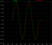
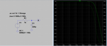
See this images of the impulse like I use for the Amplifier, but this time in a simple RC circuit.
The output is delayed by 208nS in all the audio band, and the current in R has the same behavior than the current on the VAS transistor.
In the amplifier the capacitor is the miller cap .
It is very similar to the feedback amplifier response
Attachments


Last edited:
So in your opinion the LG probe should be connected like the circuit on the right, that gives the OL gain like the simple miller ?
what is the meaning of YMMV , it is " You Make Me Vomit "
Normally, YMMV = "Your mileage may vary", but I like your variant better 😀

Dadod
I used a very simple simulation of a (non-Miller) amplifier. The input signal is not delayed with any RC network. The output is through a resistive divider load (7.75 ohms in series with 0.25 ohms) with a fine adjustment so that the output voltage is measured at 1/G where G is the gain of the amp) so that the plotted voltages are the same.
There is no Miller delay capacitor but there is an inclusive compensation capacitor.
RC networks give a very nearly constant delay (=R*C) at frequencies below where there is a significant phase shift, so you only start to see the phase shift significantly changing around f=1/(2pi RC). The inclusive compensation capacitor in my simulations was 22pF which in conjunction with 10k feedback resistor gives 220 nS - almost exactly the simulated delay.
So in your opinion the LG probe should be connected like the circuit on the right, that gives the OL gain like the simple miller ?
Why do you measure OL? To find the phase/gain margin so you know if it is safe to close the loop, right? Therefor, you must measure the OL will all compensation and such in place, no?
Jan
Normally, YMMV = "Your mileage may vary", but I like your variant better 😀
Priceless!
- Status
- Not open for further replies.
- Home
- Amplifiers
- Solid State
- Feedback loop speed