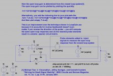
The objective was to try to understand how is the open loop of the TMC amplifier, because depending on including or not the inner feedback loop in the gain probe the outcome is very different.
The first image is the TMC with the inner miller loop included in the gain probe
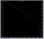
the second image is with the resistor from the TMC network connected directly to the output of the amplifier and not included on the gain probe.
Sergio, there was discussion some years ago about TMC and how to simulate Loop Gain in other tread. I use Tian probe and and always include inner loop.
Yes I know Damir, but is it the correct way ? Read my post from #149 to #152 , i try to explain how to infer the open loop gain from a closed loop amplifier.
I also use the Tian probe for OLG as well, I tried your method, and the results by comparing inputs, is not really what the Tian probe shows, as I said you're looking at the excess gain, not the OLG, but still you see the effect of tmc, extra gain in the upper registers.
I also use the Tian probe for OLG as well, I tried your method, and the results by comparing inputs, is not really what the Tian probe shows, as I said you're looking at the excess gain, not the OLG, but still you see the effect of tmc, extra gain in the upper registers.
Tian probe does not show OLG but LG or the feedback ratio.
I may have confused names,
I use the Loopgain 2 method in LT-spice, it's credited Michael-Tian. And According to the text it shows the open loop gain, derived from a closed loop system. Is there an other Tian probe..?
I use the Loopgain 2 method in LT-spice, it's credited Michael-Tian. And According to the text it shows the open loop gain, derived from a closed loop system. Is there an other Tian probe..?
I made some other tests, and it seems that the better and safer method to test the stability of the TMC is include the inner loop in gain probe, like Damir do in #161.
I may have confused names,
I use the Loopgain 2 method in LT-spice, it's credited Michael-Tian. And According to the text it shows the open loop gain, derived from a closed loop system. Is there an other Tian probe..?
Damir is right, the probe shows the loop gain, the loop gain is the open loop gain minus the closed loop gain.
Feedback, or how to be late and be on time the same time, all the time.
An excellent explanation by jan didden .
http://www.diyaudio.com/forums/blogs/jan-didden/454-feedback-how-late-time-same-time-all-time.html
An excellent explanation by jan didden .
http://www.diyaudio.com/forums/blogs/jan-didden/454-feedback-how-late-time-same-time-all-time.html
Your method is a method to find the Loopgain, the way you use the difference at the inputs is a good way to see the excess gain (the Loopgain). This is exactly what I said all along the circuit tries to create the lowest possible differential voltage, but it can only use its excess gain to do so. This is the reason why you see a good representation of the loopgain by looking at the differences at the input terminals.
Using the Loopgain 2 method in LT spice results in a curve that 27dB higer (in my case), which then must be the open loop gain.
For stability assessment I believe that you must have all compensations in place.
Using the Loopgain 2 method in LT spice results in a curve that 27dB higer (in my case), which then must be the open loop gain.
For stability assessment I believe that you must have all compensations in place.
Attachments
Last edited:
Your method is a method to find the Loopgain, the way you use the difference at the inputs is a good way to see the excess gain (the Loopgain). This is exactly what I said all along the circuit tries to create the lowest possible differential voltage, but it can only use its excess gain to do so. This is the reason why you see a good representation of the loopgain by looking at the differences at the input terminals.
Using the Loopgain 2 method in LT spice results in a curve that 27dB higer (in my case), which then must be the open loop gain.
For stability assessment I believe that you must have all compensations in place.
That is an error in LTspice example explanation. How could it show OLG if there is the feedback network in play? Try to change one of the feedback resistor and you will see that the gain changes.
Maybe because of the equation you have to insert in the plotline.
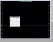
This is a quick an dirty way to determine the OLG, I have inserted a 1000GH coil in the loop, so DC is preserved and AC is broken.( this shifts the phase, so stability is harder to evaluate)
The loop Gain is also calculated using Sergios method.
This is a quick an dirty way to determine the OLG, I have inserted a 1000GH coil in the loop, so DC is preserved and AC is broken.( this shifts the phase, so stability is harder to evaluate)
The loop Gain is also calculated using Sergios method.
Attachments

Last edited:
It seems you're right and the LT-spice example is flawed. :-(
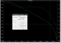
The two curves are very similar but shifted with the gain of the amplifier, The Phase is also shifted 90 degree on the plot where I have inserted a (100000GH) Coil. So I guess you have to deduct that from the plot, when using it for stability assessment. I have only one gain stage, so it would make sense that the OLG phase shift is around 90 where the gain goes to 1.
Then what is it Sergio is getting with his differential observations, it dosen't quite add up.. some gain is missing. Have to rethink the equation, I believe some division is missing.
Attachments
Ok, The circiut seek to match the gain set by the feedback ratio, it does that by throwing away the excess gain... It's the excess gain the defines the differential difference. This action is done by matching the two inputs the best possible. Then the output signal is a scaled copy of the input. This is the only way it can work. The only way the feedback can make the 1. or so order OLG linear.
Michael, in most cases, the feedback network is a simple attenuator, sending a fraction of the output signal back to the differential input with the phase inverted. That's it. The amplifier circuit simply amplifies the resulting differential input signal the same way it would do it open loop.
The phase of the feedback signal is normally not inverted (unless your circuit is inverting) The summation (subtraction) happens in the differential stage (normally in the LTP) as an action of injection of the feedback signal into the negative node of the differential..
AND Yes, I agree the feedback signal is a ratio of the input and output with reference to GND. And I also agree that the circuit amplifies the differential, But how does it arrive at that difference..?? the answer is the mechanism of feedback
The mechanism as to arrive at the desired output level is to minimise the differential difference. If you had ideal indefinite gain amplifier then the differential difference at the 2 input-nodes would be 0 Zero.
In order for feedback to work is must seek a state. Here the steady state is when the two nodes match. Then the differential work of the feedback circuit is done, and you have arrived at state of zero change. (NOT the same as Zero output level)
In a normal circuit with something like a 90 dB loop gain, then that steady state will happen approximately when the difference of the 2 nodes are matching down to app -90dB.
We need to understand what happens in infinitesimally small timesteps in order to understand the mechanism of feedback.
Last edited:
I think this example will help to understand what Jan didden was saying.
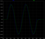
I have deliberately make the amplifier very slow ( 1us ) by change the miller cap to 100pf , and the impulse is a 50Khz sine .
The first image is the signal at the + input and the amplifier output.
The second image the current from the colector of the VAS transistor is also represented (in RED ).
The third is a zoom of the END of the impulse, and here we can see that the current in the VAS transistor reacts immediately to the end of the impulse.
So the output is following the input with 1us of delay. Even if the amplifier is too slow the feedback correction is almost immediate.
This is also valid for a change in the output, like for example the back EMF of a loudspeaker, when a impulse of current enters the output of the amplifier, the amplifier reacts immediately to this change.
Attachments


Last edited:

I don't think that there has been any claiming that time is the issue, there's is loop time in everything. In a cable speed is that of app 2/3 of light, the timing error in feedback for audio is a non issue.
where we don't see eye to eye in in the differential mechanism. where my claim of the differential nature is to seek lowest possible difference. This is a must otherwise the circuit has no way of finding a balance. A control mechanism regardless of nature being electrical mechanical or biological alway needs to seek a state. In an amplifier that state is to match the two input nodes to each other. in Ideal amplifier it can, in our non ideal circuits it can only get as close as the loop gain.
Jan you ridicule me and say I'm wrong and I dont understand. Fact is that that is easy. If you have a different and better (more correct) understanding, then please tell me where I Am wrong and show me how an amplifier finds its balance regardless of its very unlinear OLG.
For what I have seen, including Sergio's Loop-gain calculations from the two input nodes, is exactly proof on my claims.
Last edited:
Michael In the third picture #176 look at the moment the impulse stops.
Even that the input voltage is still higher than the output at the moment the impulse stops (30mv), the current in the vas stage is no longer decreasing but starts to increase.
And this goes against your claim that the amplifier always seek lowest possible difference.
But at the end the input and output will mach.
- Status
- Not open for further replies.
- Home
- Amplifiers
- Solid State
- Feedback loop speed