I'm collecting parts together to build an M2. I already have a B1 buffer but I am wondering - is unity voltage gain is enough for the M2? I should think it's ok right?
Cheers
My room is small so I don't think I use too much power. I used a
cd player directly into the M2. Variable volume control was used
on the cd player. For me, it was loud enough. The max output
of the cd player was around 2V RMS.
Dennis
Thanks Dennis. My situation is medium size room and not so efficient speakers, however I think it should be okay. Will try and see!
Dear all;
I have put together a Mouser BOM, and exported it to a google spread sheet.
It can be found here:
https://docs.google.com/spreadsheets/d/1iR01w9395KnLCubzezIL6BdYyVRI1vBBPMfFm71SDy8/edit?usp=sharing
A few comments:
All resistors 1/4 Watt, except where noted.
Had to guess on voltage of the Caps, feel free to comment, and I will change as needed
Not sure on the Pot, so used the same one as suggested for F5
Only order one set of IRFP as matching is not REQUIRED ( I think ) again, feel free to comment.
Dave
I wanted the trimmer's adjustment screw to face the top of the case, so I used the Bourns 3296-P model: 652-3296P-1-502LF .
For C1 you selected the same one I used. For C2 I used the Silmic II and for C3 I picked a Panasonic, this one: 667-EEU-FR1E332.
For C1 you selected the same one I used. For C2 I used the Silmic II and for C3 I picked a Panasonic, this one: 667-EEU-FR1E332.
Regarding the MOSFETS, there is no matching between N and P devices, but pay attention to what Nelson said earlier in this thread.
If the Vgs difference between the devices in a given channel is larger than between typical Fairchild ones, you may have to tweak the effective value of the trimmer to be able to set the output offset to 0.
...This used the Fairchild output devices and pot location assumes that P channel Vgs is slightly higher than N. You can use other devices...
😎
If the Vgs difference between the devices in a given channel is larger than between typical Fairchild ones, you may have to tweak the effective value of the trimmer to be able to set the output offset to 0.
Dear all;
I have put together a Mouser BOM, and exported it to a google spread sheet.
Where's R5?
Hello to our US based friends! I've a request for help if anyone is inclined to do so. With a GB on PCB's done there's obviously a few of us who'll be chasing the edcor transfo's. Whilst very reasonably priced the shipping costs are ...exciting!
Anyone know of any alternate ways of sending transformers from the US to Australia?
Anyone know of any alternate ways of sending transformers from the US to Australia?
Could possibly do a group buy if there is enough interest.Hello to our US based friends! I've a request for help if anyone is inclined to do so. With a GB on PCB's done there's obviously a few of us who'll be chasing the edcor transfo's. Whilst very reasonably priced the shipping costs are ...exciting!
Anyone know of any alternate ways of sending transformers from the US to Australia?
Could possibly do a group buy if there is enough interest.
I get the impression from earlier in this thread that the postage seems to be volume invariant, so splitting the cost a number of ways would help.
I'd sear I got the jensens for the f6 across to us for waaaay less.
Got a few minutes in before starting the day job.
BOM edited as per comments
R5 added, Caps Changed, pot changed.
Link to Mouser here:
Project & Cart Sharing | Mouser
Access ID: e2fb9dfa77
When I get some off the clock time I will update the Google sheet as well Just in case you are not a Mouster Fan
Dave
BOM edited as per comments
R5 added, Caps Changed, pot changed.
Link to Mouser here:
Project & Cart Sharing | Mouser
Access ID: e2fb9dfa77
When I get some off the clock time I will update the Google sheet as well Just in case you are not a Mouster Fan
Dave
Added the Visshay Alternative
Added the 3W R13 and R14
Been sticking with 5% rather than 1%, build a Pete Millett Starving student with the 5% rather than the 1%, and could not really hear anything bad, and did a bunch of reading and, not to start the debate all over, but it seems that there is still disagreement!
Dave
+ 4 x 667-ERX-3SJR47
Added the 3W R13 and R14
Been sticking with 5% rather than 1%, build a Pete Millett Starving student with the 5% rather than the 1%, and could not really hear anything bad, and did a bunch of reading and, not to start the debate all over, but it seems that there is still disagreement!
Dave
Got a few minutes in before starting the day job.
BOM edited as per comments
R5 added, Caps Changed, pot changed.
Link to Mouser here:
Project & Cart Sharing | Mouser
Access ID: e2fb9dfa77
When I get some off the clock time I will update the Google sheet as well Just in case you are not a Mouster Fan
Dave
Thanks for doing this!
I did have a problem with the access id as it said project not found.
Never mind I missed a number.
Last edited:
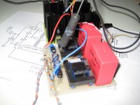
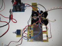
M2 frontend is sounding Mega Giga Super nice, as frontend for a headphone amp 🙂
I combined it with the upcoming DIY Headphone amp output stage and it's a keeper...
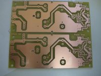
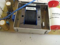
So I made a quick PCB, found some old Teko TK3710 RF-cases for shielding the Edcor's and the M2 Headphone amp is born 😀
Strange....I always hated the combination of transformers and audio...but I was so wrong... CSX1, F6 and now M2 they all sound so nice.
Makes me wonder how the M2 sounds on my big loudspeakers... 😱
I combined it with the upcoming DIY Headphone amp output stage and it's a keeper...
So I made a quick PCB, found some old Teko TK3710 RF-cases for shielding the Edcor's and the M2 Headphone amp is born 😀
Strange....I always hated the combination of transformers and audio...but I was so wrong... CSX1, F6 and now M2 they all sound so nice.
Makes me wonder how the M2 sounds on my big loudspeakers... 😱
Attachments

Very Giga Super Nice Walter 😀 😀
Bet it sounds awesome - the casing for the edcors must make the amp very silent too. Can't wait to see it all boxed up in the case!
Bet it sounds awesome - the casing for the edcors must make the amp very silent too. Can't wait to see it all boxed up in the case!
One more thing...
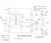
Regarding the BOM, I added a resistor and a 5 mm LED to the schematic used to create the boards. Those two components are optional but I thought some people might want to install them. The resistor's designation is R15 and the value used in other published First Watt schematics is 10K.
Regarding the BOM, I added a resistor and a 5 mm LED to the schematic used to create the boards. Those two components are optional but I thought some people might want to install them. The resistor's designation is R15 and the value used in other published First Watt schematics is 10K.
Reminder
Just a reminder that the signup for purchasing M2 Clone PCBs will close tomorrow, Friday, 1/22/2016 at 9:00 PM PST.
Just a reminder that the signup for purchasing M2 Clone PCBs will close tomorrow, Friday, 1/22/2016 at 9:00 PM PST.
Dear all;
Updated the cart with R15 and LED1
Link to Mouser here:
Project & Cart Sharing | Mouser
Access ID: e2fb9dfa77
The Google doc is here
https://docs.google.com/spreadsheets/d/1iR01w9395KnLCubzezIL6BdYyVRI1vBBPMfFm71SDy8/edit?usp=sharing
If you see anything else that is missing, please comment
Updated the cart with R15 and LED1
Link to Mouser here:
Project & Cart Sharing | Mouser
Access ID: e2fb9dfa77
The Google doc is here
https://docs.google.com/spreadsheets/d/1iR01w9395KnLCubzezIL6BdYyVRI1vBBPMfFm71SDy8/edit?usp=sharing
If you see anything else that is missing, please comment
Regarding the MOSFETS, there is no matching between N and P devices, but pay attention to what Nelson said earlier in this thread.
If the Vgs difference between the devices in a given channel is larger than between typical Fairchild ones, you may have to tweak the effective value of the trimmer to be able to set the output offset to 0.
[from zen Mod]
or value of resistor in series with pot
If I could get some input on these values, it would help me greatly. Unlike some DIY folks, I do not have a "parts bin" So, the marginal cost of a few resistors and a different value pst is often a week in lost time, and 10 times the value of the parts in shipping!
The answers are certainly in the F5 thread, and in fact, I remember scanning them, finding them is another matter

Thanks for the help
Dave
- Home
- Amplifiers
- Pass Labs
- Official M2 schematic