Yeah why not. It's interesting to see how other people get the job done. BTW there are more Pa03's to come. If we assemble our experience in one thread we can learn from each other.
I noticed you didn't use thermal paste. I guess that's just for the time being ?
You MUST add in Thermal Goop, or use a "dry" type of thermal coupler.If not grounding the heatsink you don´t need thermal paste or insulation on the LM4780 according to the manual. So i think i´ll skip it for now.
You MUST eliminate the AIR in the interface !!!!!!!!!
This is completely the wrong logic.Yes that's right clog, maybe it's a good thing to use after all. Have measured the heat on the 4780 and it seems to work pretty well as it is but i will put some on for safety.
Thank's clog☺
You MUST use a Thermal Goop.
Yeah why not. It's interesting to see how other people get the job done. BTW there are more Pa03's to come. If we assemble our experience in one thread we can learn from each other.
I noticed you didn't use thermal paste. I guess that's just for the time being ?
Thanks Clog (and AndewT & others) for sticking here. This is really a very helpful and inspiring thread..... and yes there "are more PA03 to come". 😉
My stuff will arrive in 2 days and the holidays are close by.....
 so this will give me some time to "examine" my first soldering-station.
 Talking about being a NEWBEE!!!!!!
I really like the positive vibe here. Loved your listening-impression Clog. Loafimus made me buy the same GALAXY chassis. AndrewT made me aware that i "MUST add in Thermal Goop"..... So i am well prepared😛
As far as the thermal compound, if you've ever built a PC, think of them lm4780 as your cpu. You need to make sure there is a solid connection between your processor and your heatsink so the heatsink can do its job.
Daanm, you won't be disappointed on any of the modushop stuff. Even their lower priced stuff is really top notch, but the aluminum top and bottom plates are worth it. I spent too many hours searching for a good source for chassis and won't bother looking anymore.
Daanm, you won't be disappointed on any of the modushop stuff. Even their lower priced stuff is really top notch, but the aluminum top and bottom plates are worth it. I spent too many hours searching for a good source for chassis and won't bother looking anymore.
If the chip isn't too hot, you don't have to mess with the grease but it will lower the chip temperature which is a good thing when it comes to life time.This is completely the wrong logic.
You MUST use a Thermal Goop.
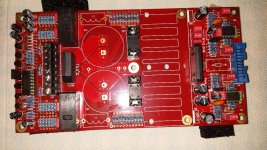
I think I am close to "finished". Finally got myself some 1 mm wire for the inductors.
Hi Clog: Can you please tel me how many windings I need?
After bolting down 🙂 the heatsink, I am going to make the "bulb tester thingy".
Plan; did it work out? What is your conclusion/opinion?
Did someone had a little time to "listen" to this nice PA03 (besides Clog)?
Peranders; Please make a little change in page 8 of your manual. The 10K "rezistory" should be R1-R11.... and thanks for the nice product!!!
Attachments
Hey Daanm, another PA03 almost ready to sing. About the inductor, I used the same diameter wire. According to the air cored inductor calculator you need about 20 turns on the shaft of an 8 mm drill. Air Cored Inductor Calculator – M0UKD – Amateur Radio Blog
Don't forget to scrape the enamel off of both ends before soldering. Good luck with powering up your build and show us the result.
Don't forget to scrape the enamel off of both ends before soldering. Good luck with powering up your build and show us the result.
I think I am close to "finished". Finally got myself some 1 mm wire for the inductors.
Hi Clog: Can you please tel me how many windings I need?
After bolting down 🙂 the heatsink, I am going to make the "bulb tester thingy".
Plan; did it work out? What is your conclusion/opinion?
Did someone had a little time to "listen" to this nice PA03 (besides Clog)?
Peranders; Please make a little change in page 8 of your manual. The 10K "rezistory" should be R1-R11.... and thanks for the nice product!!!
Looking good with your build!
Where is this manual you speak of? I just used Per-Anders blog.
As say Mr. K.Billings,in his book,Switcmode P.Supply Handbook second edition part 3 thermal management, page 3.214, fig 3.16.5,
"the effective thermal resistance of intreface between TO-3 transistor and h.sink,when using a standard mica insulator as a function of screw torque with and without thermal compound is different.
For example with the same 2 ins/lbs screw torque with 0.003" dry mica we have therm.resistance case to sink 1.4 C/W and with 0.003"mica + h.sink grease 0.4 C/W.
Thermal compound would be used on all interfaces to exclude any air voids,and the mounting screws should be tightened to the recommended torque"
Credits to Andrew T and Per-Anders
Regards
Andreas
Tanks Clog & Loafimus (and Andres B for the scientific argument by Mr. Billings)
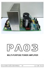
Loafimus: the manual is know by me with the file name: PA03_instr_manual.pdf
I made a screenshot of the first page.
I think i got it here: Sjöström Audio - Downloads
Loafimus: the manual is know by me with the file name: PA03_instr_manual.pdf
I made a screenshot of the first page.
I think i got it here: Sjöström Audio - Downloads
Attachments
Yes Daanm that's the one. I've got it too. (BTW is "birdie" singing already ????)
PA is asking a small fee if you want to download it, but a customer can get it for free. If I remember correctly you have to log in to the PA group buy wiki and there you will find download links for the manual, schematics and BOM.
@Loafimus, in case this doesn't work out for you I will PM it to you.
All text in this document can be found on this page:Tanks Clog & Loafimus (and Andres B for the scientific argument by Mr. Billings)
Loafimus: the manual is know by me with the file name: PA03_instr_manual.pdf
I made a screenshot of the first page.
I think i got it here: Sjöström Audio - Downloads
Sjöström Audio - PA03 Pavel Dudek's deLuxe Gainclone
The pdf document isn't updated so please go to the web page. Latest info there.
All group buy participants can download, email me for login details.
Last edited:
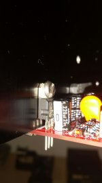
Hi Clog (and others), I just drilled some holes for the chip-clip and the two voltage regulators. But I was a little bit too much in a "hurry" (probably because I was so eager to get going again). So I also tapped m4 thread for the two voltage regulators and now the screw head is a little bit big and touches the regulator. Can that be a problem?
Thanks.
Thanks.
Hi Clog (and others), I just drilled some holes for the chip-clip and the two voltage regulators. But I was a little bit too much in a "hurry" (probably because I was so eager to get going again). So I also tapped m4 thread for the two voltage regulators and now the screw head is a little bit big and touches the regulator. Can that be a problem?
Thanks.
Can you attach a picture? Did you get a full package vreg or a bare one?
Can you attach a picture? Did you get a full package vreg or a bare one?
Thanks Loafimus. Here you see the LARGE screw (i know that it needs to be insulated, but this is just to show the situation) I hope the pic is good enough.
Attachments
Cool. As discussed earlier in this thread, my OCD would drive me nuts and I'd probably want to find a screw with a smaller head. Buuuuuttt.... It *should* be fine I'd think.
Is it flush against the heatsink? You need to make sure its making contact and insulated against the heatsink.
Is it flush against the heatsink? You need to make sure its making contact and insulated against the heatsink.
Last edited:
yeeeeah... I know what you mean... hahahaha and I am pretty sure that Clog will react the same way... 😱. So I am going to use my Saturday looking for a better screw that is going to be "visible" inside a dark black box from Italy.
HAHAHA, we are nuts!!
HAHAHA, we are nuts!!
Last edited:
Daanm that's DIY. Things go wrong sometimes. As far as I can see from the picture It seems to me that the size of the screw head isn't a problem here.
But you have to be absolutely sure that there is no electrical contact between the bolt head/shaft and the metal tab of the regulator. Check with your multimeter. Don't forget to mount the tiny shoulder washer and the insulator pad that came with your BOM. This washer insulates the head of the bolt from the tab of the regulator.
There is another option. If the legs of the regulators aren't clipped yet it seems to me that you have enough room to drill new and smaller holes and mount the regs somewhat higher on the sink. This option is especially for the OCD types here.
There is another option. If the legs of the regulators aren't clipped yet it seems to me that you have enough room to drill new and smaller holes and mount the regs somewhat higher on the sink. This option is especially for the OCD types here.
Thanks Clog, so that is what i did. (thanks for the advice) I made 2 new smaller holes a "somewhat" higher...... but I am really embarrassed to admit that my "somewhat higher" was a little too high. 🙁 . The legs of the regulators barely peeked through the board. Not ideal. So thanks (again!!) for the pm as I am now going to use the initial large m4 holes and set in m3 screws + a tiny nut on the other side. Yes I am so "lucky" to have those holes in between the ribs....... I was sooooo very close to get myself a new heatsink

I think I am not going to post any pictures anymore 😱
- Home
- Amplifiers
- Chip Amps
- Newbee build: PA03 amp (LM4780)