Picture what you get (and send into the room) when moving slightly up and down or left to right with arrays. There are many benefits from these floor to ceiling arrays. Of coarse there are compromises as well, the comb filtering interference being the biggest one. But how noticeable is that, in real life listening?
Imagine if the room were tilted back so the floor in front of you rose to listening height at the corners, how much simpler life would be 😎
1. To cut front chair legs 😱Imagine if the room were tilted back so the floor in front of you rose to listening height at the corners, how much simpler life would be 😎

Or
2. To cut rear chair legs, drivers in the corners near the ceiling..
Imagine if the room were tilted back so the floor in front of you rose to listening height at the corners, how much simpler life would be 😎
Very handy! If you use CBT arrays... don't see the point for a floor to ceiling array. 😕 Basically we're shooting for an infinite long array with use of the floor and ceiling. At least that's how I look at it. And the reason not to use shading.
The TC9 also upper frequency range directivity is so narrow that it is not hitting your side walls- little "spaciousness" above 5kHz.
The TC9 has only 30 degree dispersion (-6dB) at 16 kHz, it's -17 dB at 45 degrees off axis.
The narrowing dispersion results in less HF boost required for flat on axis response, and makes your baffle/90 degree corner waveguide diffraction "issue" not a concern.
The polars below were with the TC9 driver mounted in a 1 liter bottle, basically no baffle other than the speaker mounting flange.
Unfortunately, just noticed that I repeated the 10 degree test, so my statement above is based on the 15 degree off axis result being between the 10 and 20 degree graphs 😱.
Art
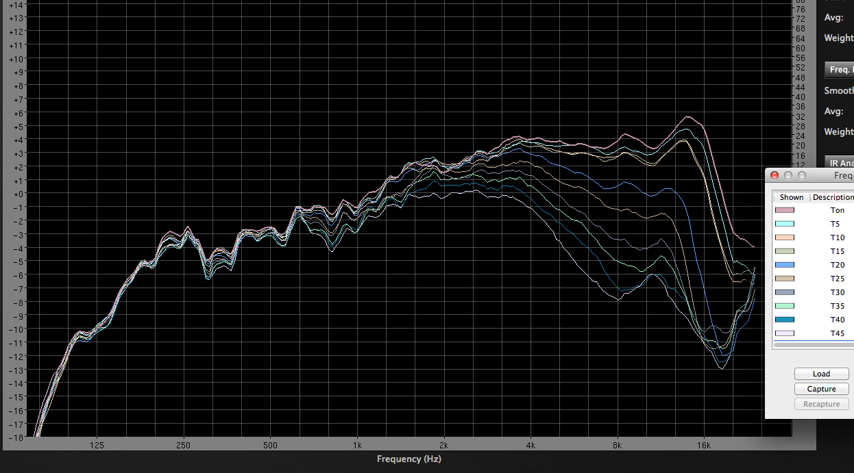
Thank for the measurement, Art. Looking at your measurement, at just below 16 kHz, the beamwidth is 40 degrees (total). At 8 kHz, it is 60 degrees. My arrays being in the corner will put this right on the opposite wall, so there will be added spaciousness. But it is important to keep this response in mind when considering the array operation in the vertical dimension also.
BTW, that is quite a uniform off-axis response. Almost no breakup. I have seen other full range drivers have a horrid off-axis response... basically, it looks nothing like the on-axis response.
And, back a few pages, I think the reference to the singer on "Let it Be" is to Paul McCartney? Lennon only sings background "ahhs" on that cut, I'm pretty sure.
And the issues with the UCA202 and 222 are that different sample clocks are used for the recording and playing streams (same nominal rate, but not in synch with each other, on is from a local crystal, the other is via a phaselock multiple on the USB clock). So you can't get a consistently precise timing using them, and you can NEVER do any signal averaging in a measurement setup with them without screwing up the results.
You are right about Paul McCartney. I thought it was Lennon, but I was wrong. Either way, the music is still brilliant 🙂
I still haven't found a sound way (pun, not intended) for doing measurements with JRiver and convolution in the loop. The FR looks good, but the impulse is wonky.
Line Array Height and Distance Measurements
So far, there have been a few questions in this thread about:
a. Comb-filtering. A line array with real drivers of small but finite size will always have comb-filtering. And this comb-filtering is audible.
b. The array response changes too much with listening height.
c. Shading is needed to extend the constancy of the beamwidth over a wider frequency range.
I made some measurements of the array in my listening room using REW. The files are in REW format and you can access them here:
https://drive.google.com/open?id=0By_atVLWB0a6TmVGTWNqMVl1ZFE
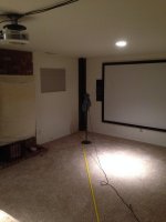
Just unzip the file and open it using REW. Individual measurements are named using distance, then height off the ground (example: 12 ft, 36 in.). Picture below shows the measurement setup. The way I did it was to setup the mic for a height and then measure along the distance, then set it for the next height and measure along the distance, and so on. The 0 in., 12 in., and 24 in. measurements at 12 ft are not super accurate in terms of distance because my mic does not go below 36 in. and I had to lay it flat along the ground to make these measurements.
So far, there have been a few questions in this thread about:
a. Comb-filtering. A line array with real drivers of small but finite size will always have comb-filtering. And this comb-filtering is audible.
b. The array response changes too much with listening height.
c. Shading is needed to extend the constancy of the beamwidth over a wider frequency range.
I made some measurements of the array in my listening room using REW. The files are in REW format and you can access them here:
https://drive.google.com/open?id=0By_atVLWB0a6TmVGTWNqMVl1ZFE
Just unzip the file and open it using REW. Individual measurements are named using distance, then height off the ground (example: 12 ft, 36 in.). Picture below shows the measurement setup. The way I did it was to setup the mic for a height and then measure along the distance, then set it for the next height and measure along the distance, and so on. The 0 in., 12 in., and 24 in. measurements at 12 ft are not super accurate in terms of distance because my mic does not go below 36 in. and I had to lay it flat along the ground to make these measurements.
Attachments
A. Comb-filtering
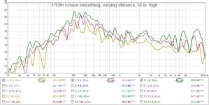
Let's look at the issues one by one starting with comb-filtering. The measurement below shows the raw (uncorrected) response of the array at 3 ft, 6 ft, and 12 ft and 36 in. above ground. The distances 3 ft, 6 ft and 12 ft represent doubling of distance. The measurement is 1/12th octave smoothed. At 3ft away, the "comb-filtering" begins just above 4 kHz. But by 6 ft, it has already smoothed out the response to about 8 kHz, and by 12 ft, there is no ripple at all up to about 16 kHz.

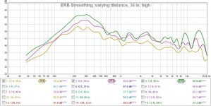
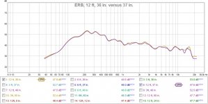
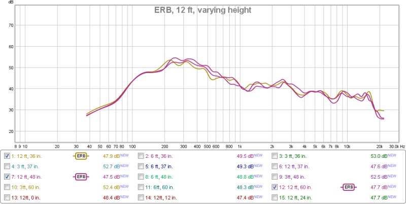
How audible is comb-filtering? REW has an ERB smoothing feature. Equivalent rectangular bandwidth is concept that helps us understand the frequency resolution of the ear. Thus a frequency response smoothed using ERBs is essentially what we will hear. The measurement below is the same as the one earlier, except ERB smoothing has been applied:

Again, a similar result is observed. Now, if you believe that what you are seeing is what you will hear then by 12 ft, the response has smoothed out quite a bit and lends itself nicely to correction.
How can we explain these measurements? Well, in Dave Smith's paper (linked earlier) he explains how in the nearfield (most home listening happens in the near-field of the array) the total response at a given distance is simply the vector sum of the magnitude and phase contribution of each unit. At smaller distances away from the array (3 ft in our case), the interunit spacing is comparable to the measurement distance. As we move away from the array, the interunit spacing becomes smaller as seen from the measurement point, and this pushes up the frequency where comb-filtering begins to appear. By 12 ft, the interunit spacing is negligible compared to the distance away from the array. At that distance, only the very high frequencies (with very small wavelengths) have appreciable phase shift from unit to unit to cause the peaks and dips. At lower frequencies, it is basically adding in phase.
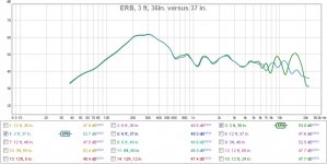
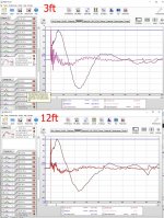
Ah, but you say that comb-filtering changes from one point to another. I made a measurement at 12 ft and 37 inches, just to compare to the one at 12 ft and 36 inches. They are basically the same! What that means is that the array response is pretty uniform along the vertical axis. More on this later. But if we look at the same measurement at 3 ft, then it's a different story. Key take-away: don't sit too close to your array.
12 ft:

3 ft:

Let's look at the issues one by one starting with comb-filtering. The measurement below shows the raw (uncorrected) response of the array at 3 ft, 6 ft, and 12 ft and 36 in. above ground. The distances 3 ft, 6 ft and 12 ft represent doubling of distance. The measurement is 1/12th octave smoothed. At 3ft away, the "comb-filtering" begins just above 4 kHz. But by 6 ft, it has already smoothed out the response to about 8 kHz, and by 12 ft, there is no ripple at all up to about 16 kHz.
How audible is comb-filtering? REW has an ERB smoothing feature. Equivalent rectangular bandwidth is concept that helps us understand the frequency resolution of the ear. Thus a frequency response smoothed using ERBs is essentially what we will hear. The measurement below is the same as the one earlier, except ERB smoothing has been applied:
Again, a similar result is observed. Now, if you believe that what you are seeing is what you will hear then by 12 ft, the response has smoothed out quite a bit and lends itself nicely to correction.
How can we explain these measurements? Well, in Dave Smith's paper (linked earlier) he explains how in the nearfield (most home listening happens in the near-field of the array) the total response at a given distance is simply the vector sum of the magnitude and phase contribution of each unit. At smaller distances away from the array (3 ft in our case), the interunit spacing is comparable to the measurement distance. As we move away from the array, the interunit spacing becomes smaller as seen from the measurement point, and this pushes up the frequency where comb-filtering begins to appear. By 12 ft, the interunit spacing is negligible compared to the distance away from the array. At that distance, only the very high frequencies (with very small wavelengths) have appreciable phase shift from unit to unit to cause the peaks and dips. At lower frequencies, it is basically adding in phase.
Ah, but you say that comb-filtering changes from one point to another. I made a measurement at 12 ft and 37 inches, just to compare to the one at 12 ft and 36 inches. They are basically the same! What that means is that the array response is pretty uniform along the vertical axis. More on this later. But if we look at the same measurement at 3 ft, then it's a different story. Key take-away: don't sit too close to your array.
12 ft:
3 ft:
Attachments
Last edited:
B. Response Variation With Height
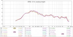
This one is simple. The measurement compares the response at 12 ft, for 36 in., 48 in. and 60 in. Note that 60 in. is the same as 24 in. off the ground due to symmetry. The response is very uniform at typical listening heights.

I did two more measurements at 12 in. and maybe 2 in. off the ground (labeled as 0 in.). I wanted to see if there was a deep cancellation near the ground and there was. The measurement compares the response at 12 ft for 36 in. (normal listening height) and 12 in. and 0 in. off the ground. Obviously, near the room boundary, the measurement gets wonky at low frequencies. But it still shows a very obvious reduction in response. This means the array is directional.

In the impulse response, there is no reflection from the ceiling or the ground. I have measured other corner speakers in the room, and there is a distinct reflection from the ceiling that is totally missing from the array measurements.
This one is simple. The measurement compares the response at 12 ft, for 36 in., 48 in. and 60 in. Note that 60 in. is the same as 24 in. off the ground due to symmetry. The response is very uniform at typical listening heights.
I did two more measurements at 12 in. and maybe 2 in. off the ground (labeled as 0 in.). I wanted to see if there was a deep cancellation near the ground and there was. The measurement compares the response at 12 ft for 36 in. (normal listening height) and 12 in. and 0 in. off the ground. Obviously, near the room boundary, the measurement gets wonky at low frequencies. But it still shows a very obvious reduction in response. This means the array is directional.
In the impulse response, there is no reflection from the ceiling or the ground. I have measured other corner speakers in the room, and there is a distinct reflection from the ceiling that is totally missing from the array measurements.
Attachments

C. Shading
In the home environment, all we really care about is a smooth response near the listening position and vertical directivity to avoid floor and ceiling reflections. Keele's CBT array uses delay and shading to improve the constancy of the beamwidth and to improve the smoothness of the response. Keele describes clearly how his curved arrays use the ground reflection to improve directivity and smooth out the response. The previous measurements already show that the response is nearly identical at 36 in, 48 in. and 60 in. at 12 ft, which means we have a pretty uniform response within the central beam. The response is also quite smooth at 12 ft. The last measurement in the post above also shows the cancellation achieved near the ground.
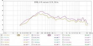
The measurement below compares the response at 6 ft and at 12 ft for 36 in. The typical line array behavior of 3 db fall per double distance can be seen to extend down to almost 200 Hz. In fact, it extends well below 100 Hz, but not before some broadening at 120 Hz. I am not sure how valid the measurements are at these low frequencies, but above 200 Hz at least, there is a constant 3 db reduction with double distance. While this does not confirm the beamwidth, I am contending that because this is "typical" line array behavior, there is vertical directivity control down to at least 200 Hz. If we had seen a more rapid fall at lower frequencies, it would mean that the array has become a point source and so the radiation is omnidirectional.

In the home environment, all we really care about is a smooth response near the listening position and vertical directivity to avoid floor and ceiling reflections. Keele's CBT array uses delay and shading to improve the constancy of the beamwidth and to improve the smoothness of the response. Keele describes clearly how his curved arrays use the ground reflection to improve directivity and smooth out the response. The previous measurements already show that the response is nearly identical at 36 in, 48 in. and 60 in. at 12 ft, which means we have a pretty uniform response within the central beam. The response is also quite smooth at 12 ft. The last measurement in the post above also shows the cancellation achieved near the ground.
The measurement below compares the response at 6 ft and at 12 ft for 36 in. The typical line array behavior of 3 db fall per double distance can be seen to extend down to almost 200 Hz. In fact, it extends well below 100 Hz, but not before some broadening at 120 Hz. I am not sure how valid the measurements are at these low frequencies, but above 200 Hz at least, there is a constant 3 db reduction with double distance. While this does not confirm the beamwidth, I am contending that because this is "typical" line array behavior, there is vertical directivity control down to at least 200 Hz. If we had seen a more rapid fall at lower frequencies, it would mean that the array has become a point source and so the radiation is omnidirectional.
Attachments
Good work! Very thorough. The measurements at different heights tell us a lot about lobbing, or not. It looks much better than I expected from an array.
The overall response is a little surprising, but that's a different topic. 🙂
The overall response is a little surprising, but that's a different topic. 🙂
Thanks Pano! The variation with height is minimal. And it sounds like that too. There is no change in tone if I am standing up or sitting down. Though most of the listening happens sitting down.
The overall response is the raw response of the array, i.e., before correction.
The overall response is the raw response of the array, i.e., before correction.
Yes, very nice detailed measurments - thanks for taking them. I know the TC9 so well and so I am very puzzled by why there is a -15dB falloff from 300Hz to the HF's? That driver is flat with the usual baffle step falloff which would make it go up at HF but you are in a corner so no baffle step here. Is it corner loaded V "horn gain" that is giving you the 300Hz boost? Must be. I guess a simple V horn model in Akabak with an array would probably show this.
No, that is typical line array response. There is a boost in the low frequencies where the summing is 6 db per doubling of area, and higher up, it sums more like 3 db per doubling of area. I think the driver's inherent response has something to do with it also. A 3.5 inch driver becomes more and more directional in the HF (see Art's measurement of the TC9 a page or two ago). There is some corner again too, probably the reason for the 300 Hz peak.
Clearly, the overall response is troubling for people. This is of course not the final response. The final response is corrected by DRC. I could correct it manually in rePhase or in JRiver. But DRC does a much better job.
EDIT: My cabinet size also results in an underdamped response, so there is a small boost below 200 Hz, I think.
Last edited:
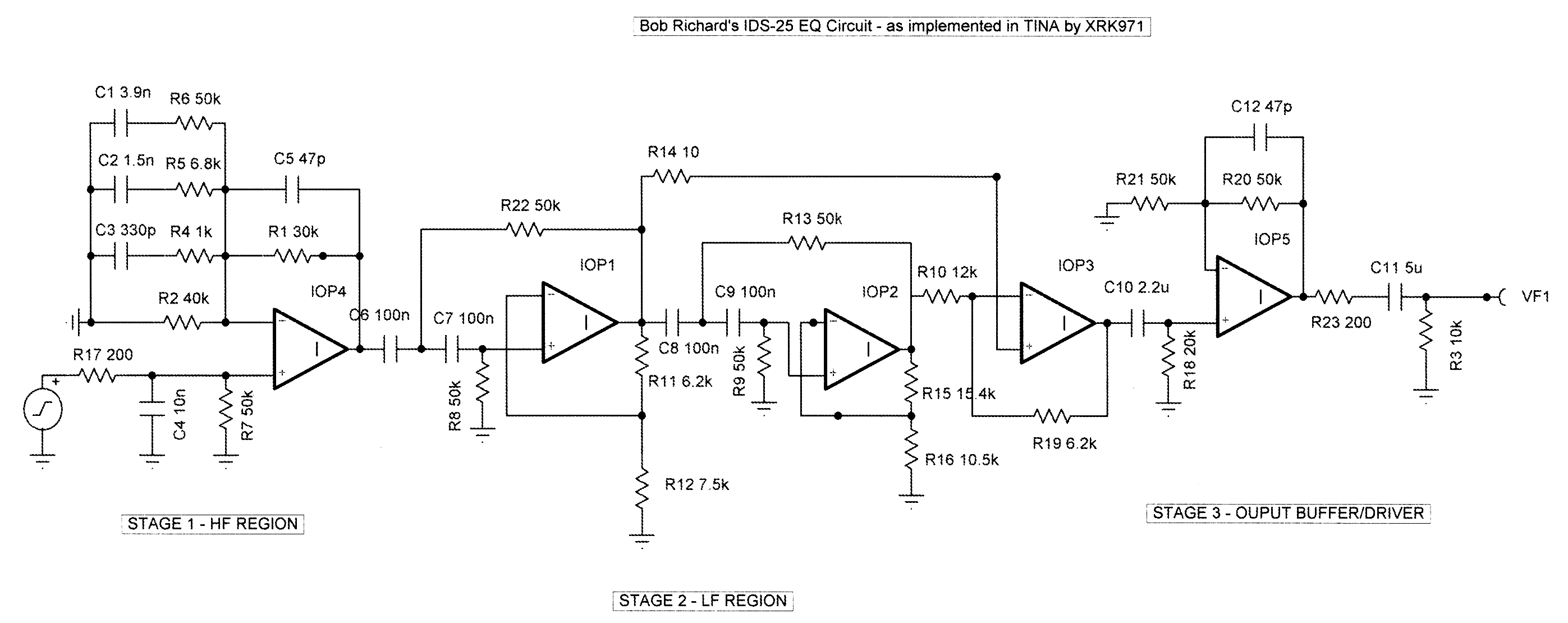
It's just that I did a comprehensive model of a 25 driver array (actually it was Wesayso's) way back when he was in design stage to see what response might look like so we could make an analog EQ circuit much like Roger Russell's. The modeled response looked almost exactly like the inverse of the Russell EQ curve. I think this was posted in the predecessor to Wesayso's Two Towers thread. Bob Richards and I then worked together to develop I think a 4 op amp active EQ that would have shaped the response. It was pretty flat in the middle but needed a boost for bass and a steep boost for HF. The 300Hz peak may be the combo of cabinet response and V horn loading. Let me see if I can find those sims. I remember running into the maximum nodes limit of Akabak at the time as I was trying to model the rear chambers and even the small holes connecting the rear chambers. Had to simplify it eventually to get it to work.
Edit: found the sims here http://www.diyaudio.com/forums/full-range/203356-cloning-ids-25s-20.html#post3631354
Here is no EQ response at 5m:
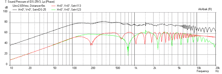
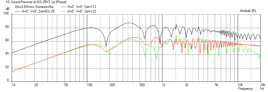
And if you put array 6in away from a back wall you get this:
So here is the predicted EQ curve based on predicted response:
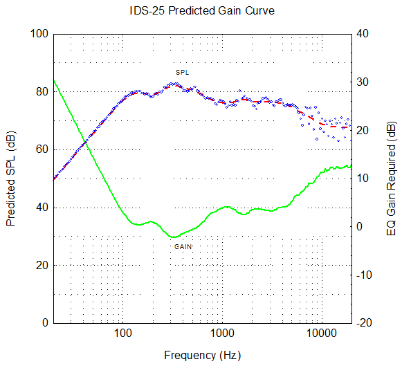
So... Looking at my sims from ages ago it looks like there is a peak at 300Hz and about a -15dB falloff. So my bad memory for not remembering my own sims!! 😀
For comparison your 12ft measurement is:
Edit: found the sims here http://www.diyaudio.com/forums/full-range/203356-cloning-ids-25s-20.html#post3631354
Here is no EQ response at 5m:
And if you put array 6in away from a back wall you get this:
So here is the predicted EQ curve based on predicted response:
So... Looking at my sims from ages ago it looks like there is a peak at 300Hz and about a -15dB falloff. So my bad memory for not remembering my own sims!! 😀
For comparison your 12ft measurement is:
Last edited:
I have been trying to find a modeling program for arrays for quite a while. There are a bunch of programs for commercial arrays and large venues. I tried one but I couldn't adapt it for the home or for my floor-to-ceiling situation. Being able to model the effect of the floor and ceiling is key.
I even emailed Don Keele and have reached out to Dave Smith with whom I've interacted before. If Akabak can do it, great. I haven't used it before. I tried it in Basta and it was not giving me good results.
I even emailed Don Keele and have reached out to Dave Smith with whom I've interacted before. If Akabak can do it, great. I haven't used it before. I tried it in Basta and it was not giving me good results.
I have been trying to find a modeling program for arrays for quite a while. There are a bunch of programs for commercial arrays and large venues. I tried one but I couldn't adapt it for the home or for my floor-to-ceiling situation. Being able to model the effect of the floor and ceiling is key.
I even emailed Don Keele and have reached out to Dave Smith with whom I've interacted before. If Akabak can do it, great. I haven't used it before. I tried it in Basta and it was not giving me good results.
As you can see from above model that Akabak works quite well. I think my prediction looks a lot like you measurement. I can give you the script if interested.
Comparing my result at 5m and your measurement at 12ft, all the key features seem to be captured and even the magnitude: the bass fall off shoulder at 130Hz, the mid bass peak at 300Hz, the gradual fall off to 1kHz, the flat shelf from 1k to 5k, followed by the final falloff to the HF's. It's all there. Amazing agreement actually.
The analog EQ circuit we developed then counters this precisely - but this has been superceded by DSP now. Still, I am curious how an all analog array can sound.
Here is the analog EQ circuit that Bob Richards and I came up with to compensate for the above response:
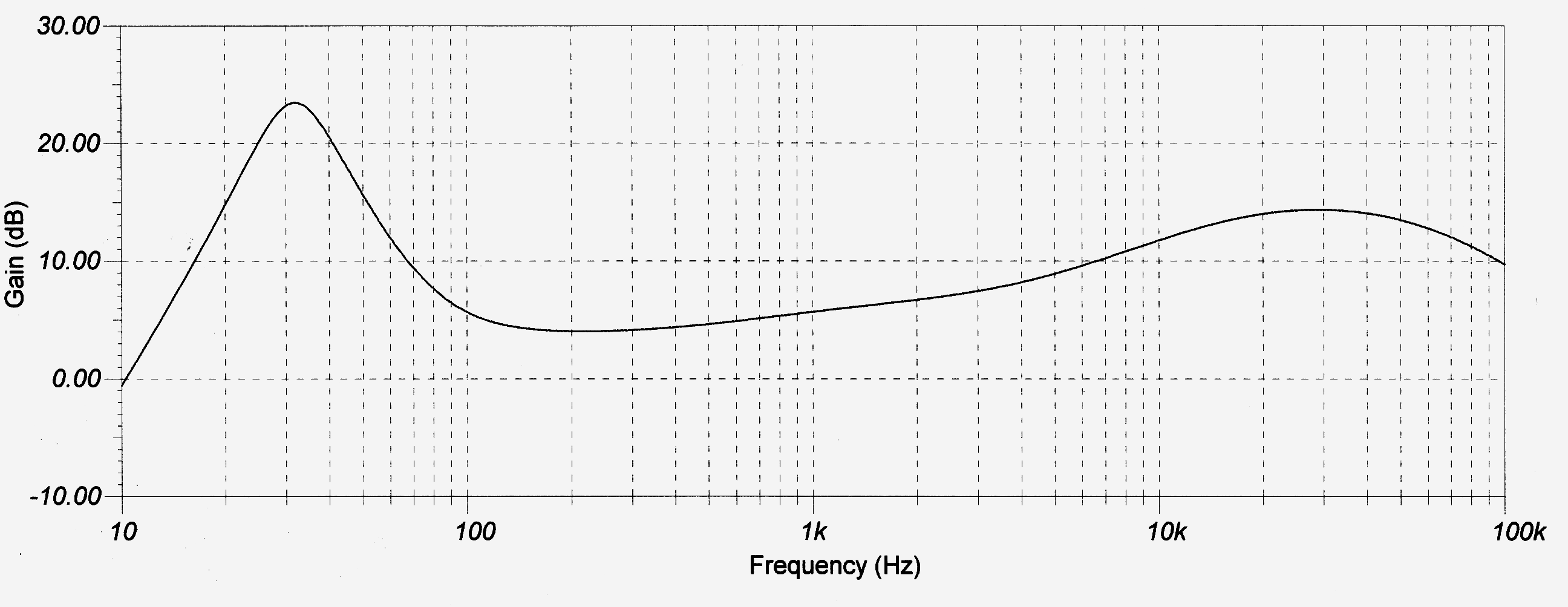
Here is analog EQ curve from circuit:
Last edited:
A few times in this thread comb filtering has been mentioned. Although I don't dispute it has the potential to be an issue, I think it is often stated as fact that it will be a problem when in actual listening is not.
One size does not fit all but here is my experience with this. I built a set of floor to ceiling LA of planar tweeters with a bank of 12, 6 1/2" mid-woofers on either side.
They are crossed at 1500Hz and doing the math, are well into the range where combing is present. I don't doubt that combing is present but I am completely unable to detect it with my ears.
A few times in this thread comb filtering has been mentioned. Although I don't dispute it has the potential to be an issue, I think it is often stated as fact that it will be a problem when in actual listening is not.
One size does not fit all but here is my experience with this. I built a set of floor to ceiling LA of planar tweeters with a bank of 12, 6 1/2" mid-woofers on either side.
They are crossed at 1500Hz and doing the math, are well into the range where combing is present. I don't doubt that combing is present but I am completely unable to detect it with my ears.
The sims in Akabak show that the summation of the 25 drivers at 5m is quite smooth and the comb interference visible from individual drivers (red and green represent middle and near ends, black is sum of 25).
So the more drivers you have and the tighter the spacing is the less of an effect it is.
- Home
- Loudspeakers
- Multi-Way
- Corner Floor-to-Ceiling Line Array Using Vifa TC9