Bias And Offset Problem in BA1200
Hello Friend ,
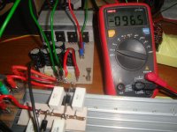
My Transistors Are Getting Hot on No load There is 160mv of offset on o/p on 52 0 52vdc supply , amp work but transistors get hot quickly can you tell ,
what did you set the values for R4 offset and R13 Bias resistors if you can share the modified segment diagram it would help a lot
i have just Damaged my 7 Pairs of Transistor twice....
hi apex sir,
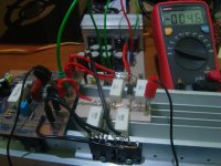
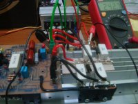
in my hand the 8.2k resistor not available, now i checked with 7.5k resistor, bias is ok,
92vdc power supply.
i feed 50hz sinewave and it clips 52v ac on output,
my 4ohm dummy load 250pcs x 1k x 5watts.
output transistors getting hot over 90degrees at 40v ac on out..
Hello Friend ,
My Transistors Are Getting Hot on No load There is 160mv of offset on o/p on 52 0 52vdc supply , amp work but transistors get hot quickly can you tell ,
what did you set the values for R4 offset and R13 Bias resistors if you can share the modified segment diagram it would help a lot
i have just Damaged my 7 Pairs of Transistor twice....
hi sir
please measure the voltage between base and collecter it should be below 0.5 volts .please check also the traces of the driver transitors if they are connected , any dry joints are very destructive especially the biasing transistors
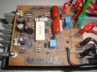
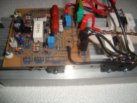
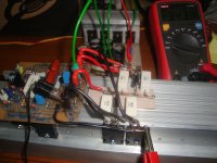
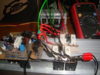
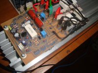
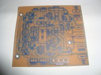
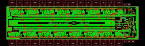
ba1200 driver board
hi apex sir,
ba1200 driver board. tested.
hi apex sir,
ba1200 driver board. tested.
Attachments
-
 DSC04212 copy.jpg185.8 KB · Views: 1,837
 -
 DSC04252 copy.jpg203.2 KB · Views: 521
 -
 DSC04251 copy.jpg195.9 KB · Views: 382
 -
 DSC04245 copy.jpg182.2 KB · Views: 378
 -
 DSC04243 copy.jpg189.5 KB · Views: 384
 -
 DSC04240 copy.jpg189.5 KB · Views: 428
 -
 DSC04239 copy.jpg199.9 KB · Views: 1,522
 -
 DSC04237 copy.jpg196.1 KB · Views: 1,605
 -
 DSC04233 copy.jpg208.5 KB · Views: 1,683
 -
 DSC04228 copy.jpg159.7 KB · Views: 1,719
hi apex sir,
i assemble the ba1200 board with 1 pair output and dc 60v psupply, but the problem is dc offset out 15v. why?
1k resistor for bias.
i assemble the ba1200 board with 1 pair output and dc 60v psupply, but the problem is dc offset out 15v. why?
1k resistor for bias.
MR MILE; it's some equivalent tu use for NE5532 for the protector you have posted, to the ampplifier B1200?
Last edited:
MR MILE; it's some equivalent tu use for NE5532 for the protector you have posted, to the ampplifier B1200?
TL072, MC4558, MC33078... many dual OP amps can be use, but this is not protect this is balanced input and limiter circuit.
No, your transformer shows three connections to Power Ground. These will short some of the windings during different phases of the mains waveform.
sir andrew , can this work,thank you
Attachments
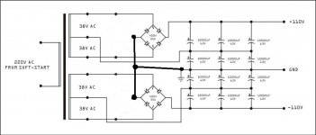
That looks like it should work.
I have never done it, so check using a Mains Bulb Tester to power ON.
That may be the only way to get +-110Vdc from 63V capacitors.
I have never done it, so check using a Mains Bulb Tester to power ON.
That may be the only way to get +-110Vdc from 63V capacitors.
I once used 40 caps in a similar configuration.... didn't blow up anything, however on one + 90v rail, one bank of caps was +48v, the other +42v.... My problem was there was no auxiliary ground since the trafo only had one center tap... so the voltage would sometimes float. The addition of some 2k resistors helped, but being 63v caps, I didnt have a huge problem, but I would not advise doing it that way...
The way you have it configured, it should be rock solid.
The way you have it configured, it should be rock solid.
For commercial work, PA and sound reinforcement, use a transformer rated at 1.5times to 2times the maximum output power.
I.e. for a 1000W power amplifier use a transformer rated at 1500VA to 2kVA.
I.e. for a 1000W power amplifier use a transformer rated at 1500VA to 2kVA.
- Home
- Amplifiers
- Solid State
- 1000W Simple PA Amplifier