Btw, any idea on how much more they would charge you more per board if you ordered gold plated vs solder clad?
According to their online ordering system gold raises my cost per board $3.20. A new order usually incurs a $100 per order tooling charge, which is not charged on a reorder. A reorder does not allow any changes. I order boards in lots of 50, or sometimes 100 for the SSE. This could add another $1 or $2 to that price.
I'm not sure if the tooling charge would be waived if I called up and talked to someone. I had to pay the $100 to have the silkscreen changed to SSE when some high powered lawyers said that I could not use the old name, even though only the silkscreen was changed....
It is likely that if you start offering gold plated PCBs going forward and charge customers an extra $5, it will not hurt your sales... Just saying 🙂
What are the advantages of a gold plated pcb over a regular solder clad board?
Are there dissimilar metal corrosion type problems over long term use?
Win W5JAG
Are there dissimilar metal corrosion type problems over long term use?
Win W5JAG
Back in the 60's through the mid 80's gold was the standard coating for MIL spec, and other high reliability PC boards. Look at all the old military, Hewlett Packard, and other high dollar electronic stuff.
It can be stored for 50 years without surface corrosion, and has a very high affinity for solder. Ask anyone who has ever worn gold jewelry near a wave solder machine or any other equipment with molten solder.
We used gold for some PC boards at work, but it was phased out as the cost of gold went through the roof. It is still used in select areas on boards where a pressure contact is used, since it doesn't corrode and is soft enough for good contact.
All of this assumes that the gold is properly applied, and thick enough to be useful. When we put down gold in a connector, pressure contact area, or test probe point, there was a nickel barrier between the gold and the bare copper. This is to prevent the copper from corroding when the contact with a hard metal (the connector) eventually wears through the gold.
The high cost of gold has created a market for other materials for corrosion resistance and hardened contact surfaces. Entek "organic metal" has replaced gold in all but the most demanding applications. There are others as well, we used Entek.
There are others as well, we used Entek.
Now you are talking my language! In my previous company, I was PCB Design Manager and PCB Commodity Team Manager. We spent a LOT of time in Asia and the North America visiting and auditing PCB shops. We also did a huge study on the various surface finishes. We ended up using lead-free HASL for the bulk of the work and gold for the high-reliability safety application boards.
The Pb-free HASL was a struggle as it does not want to flow without the lead, but we got educated on the chemistry and resolved that problem as well by having the suppliers monitor the nickel content in the dip tanks.
Likewise for gold they need to ensure a sufficient nickel seed layer to avoid black pad.
Fun stuff!
Hello everyone:
Two years ago (Geez, already??? ), I stumbled upon George's Tubelab site and this forum. As someone that has put simple kits together, knows which way to hold the soldering iron and knows enough electronics to be dangerous, I decided to try my hand as the SPP amp.
The board went up fast (I have been able to solder SMT components before, so a hole through board was easy), but getting the Power transformer (an Edcor XPWR008-120) and the output one (CXPP25-MS-8K with a tap at 23% for UL connection) took about two months. Once they got here, life got in the way, and things sat on my bench downstairs.
A year ago, during the Christmas holidays, instead of working on the SPP, I put together a Elekit TU-8200 (instant gratification sometimes wins).
This year I decided that I was going to have some progress.
Trying to remember all the post I had read before and all the info on the forum was not gonna happen, so I had to start almost over. Finally today I hooked everything up and threw the switch.
No FIRES! No magic smoke! Fuse held!😀
No right channel 😕 ! Darn it, what?
One of the grid wires was loose. Fixed. Now I have stereo🙂! The amp is quiet, a tiny bit of hum but it will improve when I clean up all the wiring and have a proper ground. Whew! Now to make it pretty! Hopefully it won't take another 2 years...
In retrospect, I am a bit of a philistine. Instead of getting new EL-84's, I raided my junk collection of European tube radios (I have about 10 and only three work. Never got around to fix the others...see a trend🙄?) and found four vintage El-84. I am using those. Someone is going to yell at me for this ...
...
But the amp? To paraphrase Frankenstein: It's alive, it's alive it's alive !😀
Marco
Two years ago (Geez, already??? ), I stumbled upon George's Tubelab site and this forum. As someone that has put simple kits together, knows which way to hold the soldering iron and knows enough electronics to be dangerous, I decided to try my hand as the SPP amp.
The board went up fast (I have been able to solder SMT components before, so a hole through board was easy), but getting the Power transformer (an Edcor XPWR008-120) and the output one (CXPP25-MS-8K with a tap at 23% for UL connection) took about two months. Once they got here, life got in the way, and things sat on my bench downstairs.
A year ago, during the Christmas holidays, instead of working on the SPP, I put together a Elekit TU-8200 (instant gratification sometimes wins).
This year I decided that I was going to have some progress.
Trying to remember all the post I had read before and all the info on the forum was not gonna happen, so I had to start almost over. Finally today I hooked everything up and threw the switch.
No FIRES! No magic smoke! Fuse held!😀
No right channel 😕 ! Darn it, what?
One of the grid wires was loose. Fixed. Now I have stereo🙂! The amp is quiet, a tiny bit of hum but it will improve when I clean up all the wiring and have a proper ground. Whew! Now to make it pretty! Hopefully it won't take another 2 years...
In retrospect, I am a bit of a philistine. Instead of getting new EL-84's, I raided my junk collection of European tube radios (I have about 10 and only three work. Never got around to fix the others...see a trend🙄?) and found four vintage El-84. I am using those. Someone is going to yell at me for this
...But the amp? To paraphrase Frankenstein: It's alive, it's alive it's alive !😀
Marco
First Amp Build!
Well, after reading about valve amplifiers and looking over many kits, I've decided on the Tubelab SPP. I've waded through all 63 pages of this thread and hopefully gleaned the most important info for my planned build.
This is my first diy amp, so I'm a definite noob, but I have done a few kits - a mate & I designed, sourced and kitted 100 aquarium controllers a few years back - 10x240VAC outlets for temp. control, timers (lights, pumps, dosing), SMS alarms, etc based around a simple pic - kitting them up was quite a process, then everyone wanted us to solder their components to the PC boards for them. But on amp building I've got a lot to learn!
Anyways, I'm hoping between the good folk here, George's detailed manual, a few ol' mates and the resources of the greater interweb, I can cobble together something functional!
The board and parts kit arrived from George today (thanks George!) and as soon as the new tips for my soldering iron turn up, I will start on that.
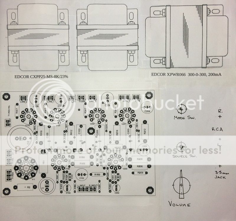
Transformers from Edcor (XPWR066 & CXPP25-MS-8K/23%) – built to order, so I'm waiting patiently for those to ship.
I've gone with JJ tubes – 4 x EL84, 2 x 12AT7/ECC81 and a GZ34/5AR4 Rectifier tube. Chassis will be 2.5mm Aluminium plate for the top and rear panels with a basic black finish, mounted in a simple box made from recycled Huon Pine with a clear finish. RCA and Jack Inputs, Source Switch, Power/Mode Switch and Volume Pot will all be mounted through the top plate, with IEC power inlet/switch/fuseholder and 4, 8 and 16ohm speaker terminals mounted through the rear panel.
I've got my head around the wiring notes between the OPT's and board by Russ on p58 in post #579: http://www.diyaudio.com/forums/tubelab/148694-tubelab-simple-p-p-58.html#post3482585
I plan on installing 470pf (mid range) capacitors for C101/C102 for feedback – is this the correct part?:
CD15FD471FO3F Cornell Dubilier Electronics (CDE) | Capacitors | DigiKey
I was going to use a 4DPT 3pos. toggle switch with 'middle off' to switch between Pentode and ultralinear. I've looked at the schematics by Ian444 on p36 post #353: http://www.diyaudio.com/forums/tubelab/148694-tubelab-simple-p-p-36.html#post2568175
but I'm still getting my head around how to correctly wire the switch and am leaning towards just setting it up as ultralinear for now. If I follow Russ's wiring setup linked to above, will that have the amp setup for ultralinear mode? Sorry for such a noob question, but my head is hurting a little over this...
I intend using the following key components:
Edcor XPWR066 (240VAC - I'm in Oz) 300-0-300, 200mA
https://www.edcorusa.com/xpwr066
Edcor CXPP25-MS-8K/23%
https://www.edcorusa.com/cxpp25-ms-8k-23
Volume Pot.: DACT 21step 50k,
Dact Type 21 Stepped Attenuator Potentiometer 50K 300B | eBay
Mode Switch – Pentode/Power Off/Ultralinear - 4DPT 3 pos. on/off/on toggle:
10A 380VAC 15A 250VAC 3 Position 4PDT on Off on 12 Pin Toggle Switch | eBay
Source Switch - RCA/Jack - 4DPT 2 pos. on/on toggle:
On on 2 Position 4PDT Latching Toggle Switch AC 15A 250V 10A 380V | eBay
Power inlet/switch/fuseholder:
IEC Fuse Chassis Male Power Plug with Switch | Moulded Leads | Distribution & Interconnect | Power Products Electrical | PRODUCTS | PP4003 | Jaycar Electronics
I'm not much a draftsman, but here's a pic of the planned layout (310Wx300D) for the top plate:
If anyone can advise me on the Pentode/Ultralinear conundrum please do, or if you think I've got anything wrong or am missing something, feel free to let me know!
Cheers,
Rob
Well, after reading about valve amplifiers and looking over many kits, I've decided on the Tubelab SPP. I've waded through all 63 pages of this thread and hopefully gleaned the most important info for my planned build.
This is my first diy amp, so I'm a definite noob, but I have done a few kits - a mate & I designed, sourced and kitted 100 aquarium controllers a few years back - 10x240VAC outlets for temp. control, timers (lights, pumps, dosing), SMS alarms, etc based around a simple pic - kitting them up was quite a process, then everyone wanted us to solder their components to the PC boards for them. But on amp building I've got a lot to learn!
Anyways, I'm hoping between the good folk here, George's detailed manual, a few ol' mates and the resources of the greater interweb, I can cobble together something functional!
The board and parts kit arrived from George today (thanks George!) and as soon as the new tips for my soldering iron turn up, I will start on that.
Transformers from Edcor (XPWR066 & CXPP25-MS-8K/23%) – built to order, so I'm waiting patiently for those to ship.
I've gone with JJ tubes – 4 x EL84, 2 x 12AT7/ECC81 and a GZ34/5AR4 Rectifier tube. Chassis will be 2.5mm Aluminium plate for the top and rear panels with a basic black finish, mounted in a simple box made from recycled Huon Pine with a clear finish. RCA and Jack Inputs, Source Switch, Power/Mode Switch and Volume Pot will all be mounted through the top plate, with IEC power inlet/switch/fuseholder and 4, 8 and 16ohm speaker terminals mounted through the rear panel.
I've got my head around the wiring notes between the OPT's and board by Russ on p58 in post #579: http://www.diyaudio.com/forums/tubelab/148694-tubelab-simple-p-p-58.html#post3482585
I plan on installing 470pf (mid range) capacitors for C101/C102 for feedback – is this the correct part?:
CD15FD471FO3F Cornell Dubilier Electronics (CDE) | Capacitors | DigiKey
I was going to use a 4DPT 3pos. toggle switch with 'middle off' to switch between Pentode and ultralinear. I've looked at the schematics by Ian444 on p36 post #353: http://www.diyaudio.com/forums/tubelab/148694-tubelab-simple-p-p-36.html#post2568175
but I'm still getting my head around how to correctly wire the switch and am leaning towards just setting it up as ultralinear for now. If I follow Russ's wiring setup linked to above, will that have the amp setup for ultralinear mode? Sorry for such a noob question, but my head is hurting a little over this...
I intend using the following key components:
Edcor XPWR066 (240VAC - I'm in Oz) 300-0-300, 200mA
https://www.edcorusa.com/xpwr066
Edcor CXPP25-MS-8K/23%
https://www.edcorusa.com/cxpp25-ms-8k-23
Volume Pot.: DACT 21step 50k,
Dact Type 21 Stepped Attenuator Potentiometer 50K 300B | eBay
Mode Switch – Pentode/Power Off/Ultralinear - 4DPT 3 pos. on/off/on toggle:
10A 380VAC 15A 250VAC 3 Position 4PDT on Off on 12 Pin Toggle Switch | eBay
Source Switch - RCA/Jack - 4DPT 2 pos. on/on toggle:
On on 2 Position 4PDT Latching Toggle Switch AC 15A 250V 10A 380V | eBay
Power inlet/switch/fuseholder:
IEC Fuse Chassis Male Power Plug with Switch | Moulded Leads | Distribution & Interconnect | Power Products Electrical | PRODUCTS | PP4003 | Jaycar Electronics
I'm not much a draftsman, but here's a pic of the planned layout (310Wx300D) for the top plate:
If anyone can advise me on the Pentode/Ultralinear conundrum please do, or if you think I've got anything wrong or am missing something, feel free to let me know!
Cheers,
Rob
Rob,
G'Day!
One observation - your layout has the power transformer on the right side of the board; the PCB's connections to the power transformer are on the left side. It is better to place the PT on the side of the PCB power connections.
G'Day!
One observation - your layout has the power transformer on the right side of the board; the PCB's connections to the power transformer are on the left side. It is better to place the PT on the side of the PCB power connections.
location of power transformer
Hi,
I agree with zman01. Another benefit is, that the power transformer moves farer away from the input jacks.
Rob,
G'Day!
One observation - your layout has the power transformer on the right side of the board; the PCB's connections to the power transformer are on the left side. It is better to place the PT on the side of the PCB power connections.
Hi,
I agree with zman01. Another benefit is, that the power transformer moves farer away from the input jacks.
Thanks for the feedback! I had originally had the layout on the opposite 'hand' with the PT on the left and board on the right. But my concern was the large Rectifier tube was a bit close to the controls. Physically I'll have space to route the PT wires to access the board, but yes, it is the longest run. I'll give it some more thought - Cheers!One observation - your layout has the power transformer on the right side of the board; the PCB's connections to the power transformer are on the left side. It is better to place the PT on the side of the PCB power connections.
Thanks! I had been mindful to keep the input jacks well separated from OPT, but it looks like another draft of the layout might be in order!I agree with zman01. Another benefit is, that the power transformer moves farer away from the input jacks.
Cheers,
Rob
I finally put everything together.
This is a SPP connected in UL. PT is Edcor XPWR008 and OT's are Edcor CXPP25-MS-8K with a 23% tap. The enclosure is an Hammond with walnut. I wish I had gone metal. The enclosure is very is a bit small for this...
As luck would have it, I had on hand a blue spray paint that matches the Edcor bells. I also added a green 6.3 V jewel light. Looks like a old-timey guitar amp. I am waiting for a better pot (I have a Alps 50 on order).
Everything seems to work ok. The PT is barely warm after 1/2 hour, and so are the OT. I cannot say the same with the tubes 🙂
It only took two years...
Now to the next one...
Marco
Neat, compact build Marco!
Are your connections for Ultralinear the same as outlined by Russ on p58 in post #579?:
http://www.diyaudio.com/forums/tubelab/148694-tubelab-simple-p-p-58.html#post3482585
That colour match is amazing - what brand/colour was that?
Are your connections for Ultralinear the same as outlined by Russ on p58 in post #579?:
http://www.diyaudio.com/forums/tubelab/148694-tubelab-simple-p-p-58.html#post3482585
That colour match is amazing - what brand/colour was that?
I bought a SPP board to use while I restored a Dynaco ST35. The Dynaco was intact but badly rusted. So I used the Dynaco 6BQ5's, power and output transformers with the SPP board. When wired as ultra linear it sounded great. I tried Pentode and to me in comparison it sounded punchy, harsh and shrill. I tried various capacitors in the feedback and they didn't help. I took the feedback caps out and went back to ultra linear. Eventually the Dynaco went back together.
So, what to do with the SPP board? I found some 6CW5's and used a power transformer from an old CGA monitor. I bought new Edcor outputs with 3.8k primary. Same thing, ultra linear sounded great 😀 and Pentode didn't. 😡
I would suggest you begin by wiring your SPP as ultra linear. Use it for a while and get to know the sound. Rewire it for Pentode and try various caps in the feedback circuit. Then decide if you want it switch able. Seems like a lot of work with little reward. Is there anyone who prefers SPP Pentode?
Best of luck to you!
Neat, compact build Marco!
Are your connections for Ultralinear the same as outlined by Russ on p58 in post #579?:
http://www.diyaudio.com/forums/tubelab/148694-tubelab-simple-p-p-58.html#post3482585
That colour match is amazing - what brand/colour was that?
The connections I have were found in a post on the Tubelab simple P-P thread (I don't remember which page, sorry) but I downloaded the schematic which I have attached. The author is identified so it should be ok.
The color was pure luck. I checked my basement to see what spray paint I had on had and this can of Krylon Patriotic Blue #2329 (bought who knows when for who knows what project) was sitting on a shelf. The match is very good.
Attachments
Thanks Fusor - That's sounds like a sensible plan!I would suggest you begin by wiring your SPP as ultra linear. Use it for a while and get to know the sound. Rewire it for Pentode and try various caps in the feedback circuit. Then decide if you want it switch able. Seems like a lot of work with little reward. Is there anyone who prefers SPP Pentode?

I found the original(I think) post 353 page 36:Neat, compact build Marco!
Are your connections for Ultralinear the same as outlined by Russ on p58 in post #579?:
http://www.diyaudio.com/forums/tubelab/148694-tubelab-simple-p-p-36.html#post2568175
Marco
Thanks Marco! I have a copy of that schematic, I probably should have studied it more closely - will do now! 😉I found the original(I think) post 353 page 36:
http://www.diyaudio.com/forums/tubelab/148694-tubelab-simple-p-p-36.html#post2568175
This is the connection list by Russ (on p58 in post #579) that I've been talking about:
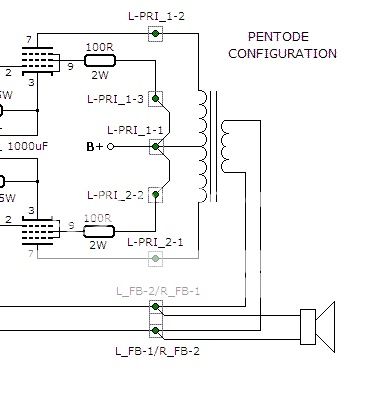
I've spent a bit more time studying and finally worked out the difference bewtwen the Pentode and Ultralinear Schematic's that Ian444 linked on p36, post #353:
http://www.diyaudio.com/forums/tubelab/148694-tubelab-simple-p-p-36.html#post2568175
I've edited the pics to more clearly show the diff for any other newb:
Pentode:
Ultralinear:
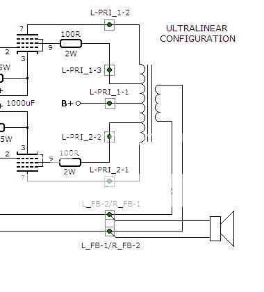
So I'm pretty sure I've confirmed to myself that Russ's connection list is for Ultralinear with feedback (if C101/201 installed) - Apologies to those (most) of you who got their head around it all years ago! ;-)
Cheers,
Rob
Well, this is the wiring diagram for the Hammond 1650FA OPT:
Each channel on the SPP has 3 sets of terminals for the OPTs. So for example, from left to right along the back of PCB:
Left Channel
- L-PRI_2
- 2 - V102 screen - primary blue/yellow wire
- 1 - V102 plate - primary blue wire
- L-PRI_1
- 3 - V101 screen - primary brown/yellow wire
- 2 - V101 plate - primary brown wire
- 1 - primary red wire
- L_FB
- 2 - Ground - secondary black wire
- 1 - Feedback - secondary (green, yellow, or white)
Right Channel
Please note that L_FB and R_FB are mirrored! Also note that if you do decide to use feedback (by installing C101/201), you may need to swap the PRI_1 and PRI_2 secondary connections on each channel to get the right phasing (leave the red wire where it is). I can't remember if I had to or not. You'll know if it's wrong if you get loud squealing out of your speakers with feedback connected.
- R-PRI_2
- 2 - V202 screen - primary blue/yellow wire
- 1 - V202 plate - primary blue wire
- R-PRI_1
- 3 - V201 screen - primary brown/yellow wire
- 2 - V201 plate - primary brown wire
- 1 - primary red wire
- R_FB
- 2 - Feedback - secondary (green, yellow, or white)
- 1 - Ground - secondary black wire
I've spent a bit more time studying and finally worked out the difference bewtwen the Pentode and Ultralinear Schematic's that Ian444 linked on p36, post #353:
http://www.diyaudio.com/forums/tubelab/148694-tubelab-simple-p-p-36.html#post2568175
I've edited the pics to more clearly show the diff for any other newb:
Pentode:
Ultralinear:
So I'm pretty sure I've confirmed to myself that Russ's connection list is for Ultralinear with feedback (if C101/201 installed) - Apologies to those (most) of you who got their head around it all years ago! ;-)
Cheers,
Rob
- Home
- More Vendors...
- Tubelab
- Tubelab Simple P-P