re: Jazbo8
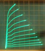
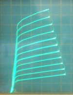
"26HU5/6KD6 pics, 50 mA/div Vert, 50V/div Horiz"
"What grid steps did you use?"
I re-checked a 26LX6 here (equivalent tube), and looks like 7 V steps. The tracer will do about 70V maximum step sweep, so 7V comes out to the maximum step size that still uses all 10 steps (10 increments) to full size. I've attached the 26HU5 followed by two different 26LX6 triode pics. Scale still 50 mA/div Vert., 50V/div Horiz.
(Woops, just noticed I had the 2nd 26LX6 pic set for 9 steps)
Then attached a 36MC6 (best one found so far) and a 36MC6 (typical) and a 36LW6 (best one found so far) in triode. All likely 7 V steps. The 36MC6 is RCA's 9 Pin Novar clone of the 26LX6/26HU5/6KD6 bunch.
Attachments

Last edited:
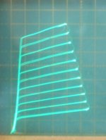
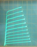
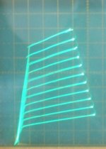
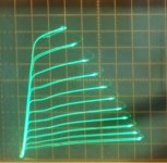
Here is a replacement pic of the 2nd 26LX6 in triode with the full 10 steps.
Then followed by the original 1st 26LX6, and then the 26HU5 for comparisons.
-----------------------------------------
A note on the g2 drive kinks:
The tubes that I have tested with fixed -Vg1, and +Vg2 stepping, do not suddenly develop a kink in some -Vg1 region like the datasheets seem to show. Rather, they gradually and smoothly develop a deeper and wider kink as Vg1 goes more negative (and +Vg2 DC bias goes more positive to compensate the idle current). Starting right at -0.1Vg1.
Attachments


Last edited:

Holy Cow!
I tried that resistor from g2 to g1 scheme (that AJT posted) on the same 26LX6 here.
I just grabbed a 2.7K resistor that was laying on the bench, and it works near perfectly!
This curve is at 50 mA/div Vert., 50V/div Horiz., -5V steps down from 55V on g2 with the 2.7K resistor to g1. (no extra resistor to ground here)
2nd curve is the previous g2 drive only curve above again (-2V on g1) for comparison. Notice how the curves have become almost equal spaced. So the g1 Beta current gain sag against the g2 1.5 expanding power law compensates beautifully.
This is a major finding.
This is so easy to do! And works so well. Insane. Where is George (Tubelab), he will want to know about this.
Just added a 3rd curve set, the 26LX6 in normal g1 drive, same scale, for comparison.
Attachments
Last edited:
I've done some measurements on the "Crazy Drive" (resistor from g2 to g1) versus straight g2 drive (0 V on g1) for the same span of plate curves to get some idea of Watt dissipations in the grids.
All curve pics: 50 mA/div Vert. and 50 V/div Horiz.
1st pic:
Crazy Drive: -5V steps down from +55V on g2 with 2.7K resistor to g1
Average current draw from the screen supply was 24 mA. Average voltage across the 2.7K resistor was 26V for a 9.6 mA avg current to the g1. Leaving 14.4 mA avg through g2. Avg. V on g1 from cathode was 2.28V
2nd pic: Standard g2 drive -6.2V steps down from +75V on g2
Average current draw from the screen supply was 16 mA. Avg. V on g2 was 44V.
So figuring Avg mA times Avg voltage for the grids to get Watts:
Crazy Drive: g1: 9.6 mA x 2.28V = 22 mW
g2: 14.4 mA x 30V = 432 mW
g2 drive: g2: 16 mA x 44V = 704 mW
Can probably figure about 4 or 5X those Wattages for peak Watts on the grids. (twice the current and twice the voltage at plate current peaks, plus some non-linear effects)
Normal operation in an Amp will be significantly less grid Watts, since the power wasteful section below the knee voltages would not be exercised there. (the curve tracer is hard on tubes)
3rd pic is conventional g1 drive.
2V steps on g1. g2 at 75V and avg current on g2 12 mA.
No mWatts for g1. 900 mW for g2.
So Crazy Drive looks pretty good for the tube's health too.
Attachments


Last edited:
The "Special Triode" scheme in the "Ham Tips" article may have been forgotten way back then because the plate curves they posted on page 3 are not very linear. They seem to have optimized for efficiency rather than linearity. Lucky thing the 2.7K g2 to g1 resistor I picked up off the bench here last night (accidentally) optimised for linearity!
I have checked the plate curves now for the low current region (for P-P crossover) and there is a gain increase issue. Apparently the higher gain g1 is taking over there in the 0 to 60 mA region. (pic #1) Not drawing enough current from the g2 to g1 dropping resistor apparently, at low signal.
So I tried a higher g2 to g1 resistor (12.7K) and that dropped the gain increase region down to 0 to 30 mA. Still not good enough for P-P. That also reduced the overall plate curves current by 15% but they still look linearly spaced. So apparently the g2 to g1 resistor value is not very critical.
Then I tried an extra resistor from g1 to cathode (like the 4D32 schematic AJT posted). (pic #2) I found 500 Ohms there nicely optimised (dropped) the low current gain region for P-P crossover purposes. (the 4D32 schematic used 20K and 100K as I recall, but that's a very different tube, and the resistors probably scale with each other)
Then I tried a 6HJ5 tube in Special Triode. (pic #3)
And then a 21HB5A tube in Special Triode. (pic #4)
Looks like most any Sweep tube will work well with this "Special Triode" scheme (really more like "Special Pentode", with the high Z out).
One might want to put some pots in initially, to optimise the Amplifier distortion profile with an FFT analyzer on the PC.
For SET (or SEST or SESP?) one might want to leave a switch or pot in for the g2 to g1 resistor. That would allow adjusting between very linear and 2nd Harmonic coloring with a knob.
First two pics are using 20 mA/div Vert. and 50 V/div Horiz.
Rest are using 50 mA/div Vert. and 50 V/div Horiz.
Pics #1 through #4 are in Special mode. #5 and #6 in conventional g2 drive mode.
Pic #1 26LX6 19V max g2 and -2V steps
Pic #2 26LX6 20V max g2 and -2.3V steps and the 500 Ohm resistor added
Pic #3 6HJ5 75V max g2 and -7V steps
Pic #4 21HB5A 78V max g2 and -7V steps
Pic #5 6HJ5 g2 mode
Pic #6 21HB5A g2 mode
Attachments

Last edited:
I rigged up some variable pots for the curve tracer with "Crazy Drive" or "Special Triode" mode circuit. Easy to tune up the circuit for any Sweep tube now.
Using both the R from g2 to g1 (Rg2g1) and the 2nd R from g1 to cathode (Rg1K).
G2 gets driven by steps down from the max. g2 supply. Rg2g1 then feeds current to g1. Rg1K controls the g1 gain when g1 is hardly drawing any current.
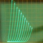
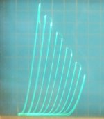
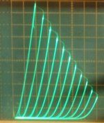
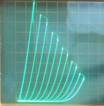
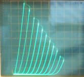
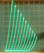
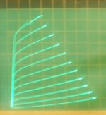
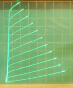
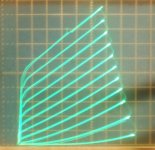
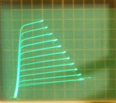
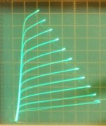
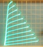
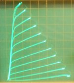
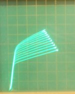
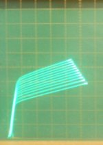
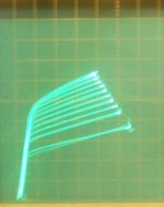
Here are some pics of the individual grid component effects. In other words, the Crazy Drive circuit, but with one or the other (g1 or g2) grid effects disabled. (by connecting g1 to 0V, or by connecting g2 to fixed Volts of about 1/2 the usual max g2 swing)
Scale for all: 50 mA/div Vert., 50V/div Horiz., +78V max for g2 swing with 7 V steps
1) 21LG6A g1 active only, g2 set to fixed 43V
2) 21LG6A g2 active only, g1 set to 0V
3) 21LG6A g1 and g2 active (full Crazy drive)
You can see the corrective effect the g1 only is making. (pic1) Being mainly current driven (positive) by the Rg2g1 (1.4K Ohm here) resistor, it loses its current gain at higher currents.
Put that together with the g2 drive only curves (pic2) and you get the almost equally spaced pic 3 curves.
There is probably a little interaction as well, since higher current from one source would be boosting the gm of the other.
added:
4) 21LG6A in normal negative biased g1 pentode mode (for comparison)
Using both the R from g2 to g1 (Rg2g1) and the 2nd R from g1 to cathode (Rg1K).
G2 gets driven by steps down from the max. g2 supply. Rg2g1 then feeds current to g1. Rg1K controls the g1 gain when g1 is hardly drawing any current.
Here are some pics of the individual grid component effects. In other words, the Crazy Drive circuit, but with one or the other (g1 or g2) grid effects disabled. (by connecting g1 to 0V, or by connecting g2 to fixed Volts of about 1/2 the usual max g2 swing)
Scale for all: 50 mA/div Vert., 50V/div Horiz., +78V max for g2 swing with 7 V steps
1) 21LG6A g1 active only, g2 set to fixed 43V
2) 21LG6A g2 active only, g1 set to 0V
3) 21LG6A g1 and g2 active (full Crazy drive)
You can see the corrective effect the g1 only is making. (pic1) Being mainly current driven (positive) by the Rg2g1 (1.4K Ohm here) resistor, it loses its current gain at higher currents.
Put that together with the g2 drive only curves (pic2) and you get the almost equally spaced pic 3 curves.
There is probably a little interaction as well, since higher current from one source would be boosting the gm of the other.
added:
4) 21LG6A in normal negative biased g1 pentode mode (for comparison)
Attachments


Last edited:
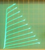
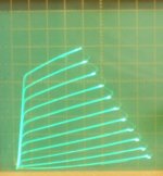
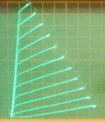
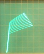
Looks like adding a low +voltage to the bottom end of the Rg1k (g1 to cathode) resistor brings the compensation to near perfection. So far I've seen from 1.4V to 4V offset (depending on tube type) to be optimum. This allows the low current level gain to smoothly taper off. Could just use a couple or three LEDs in series with the Rg1k resistor to get that voltage offset.
Not sure why this works, maybe it compensates some kind of thermal contact potential offset in the tube. (which might be allowing the g1 to operate in negative territory effectively at low plate current, messing up the g1 current gain operation there with its high Z) Before I was having to reduce the value of Rg1k too much to fix the bottom end gain, which was reducing the upper end linearity compensation too much. Now it can do BOTH well.
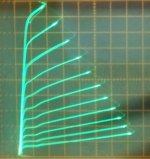
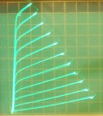
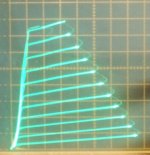
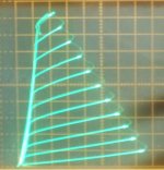
All pics are 50 mA/div Vert. and 50V/div Horiz. with the "crazy drive" or "special triode" drive circuit.
1) 35LR6 g1 only, Rg1k optimised for top range, but no 2.5V offset
2) 35LR6 g1 only, Rg1k reduced in value to compensate lower range mainly, no 2.5V offset
3) 35LR6 g1 only, Rg1k optimised for top range and the 2.5V offset for the low range
4) 35LR6 g1 and g2, Rg1k optimised, 2.5V offset (ie, full compensation)
5) 36LW6 g1 only, Rg1k optimised for top range and 4 V offset for low range
6) 36LW6 g1 and g2, Rg1k optimised, 4 V offset (full compensation)
7) 36LW6 g2 only
8) 6LB6 g1 and g2, Rg1k optimised, 1.4V offset (full compensation)
9) 36LW6 in conventional -g1 pentode (for comparison)
A 2 Volt offset worked well for the earlier 21LG6 tube.
Funny, how all the tubes look almost the same after full compensation. No kinks anymore. Sort of the "ideal tube" or the proverbial "wire with gain".
So I think the "crazy drive" or "special triode" is working well enough now to try in some Amp. Only takes a few parts added to g2 drive to make for remarkably linear performance. Should work real well for SE mode, but needs some kind of N Fdbk to lower the Zout.
If the crossover gain matching works well enough for P-P operation, then this will be a big advantage for class aB. Normally class aB, or class B, has low gm (or gain) in the low signal range, but this won't, flat gain everywhere.
I guess I should stop hogging Paul's 6KD6 Screen Drive thread!
Any further results will be in a new thread.
Not sure why this works, maybe it compensates some kind of thermal contact potential offset in the tube. (which might be allowing the g1 to operate in negative territory effectively at low plate current, messing up the g1 current gain operation there with its high Z) Before I was having to reduce the value of Rg1k too much to fix the bottom end gain, which was reducing the upper end linearity compensation too much. Now it can do BOTH well.
All pics are 50 mA/div Vert. and 50V/div Horiz. with the "crazy drive" or "special triode" drive circuit.
1) 35LR6 g1 only, Rg1k optimised for top range, but no 2.5V offset
2) 35LR6 g1 only, Rg1k reduced in value to compensate lower range mainly, no 2.5V offset
3) 35LR6 g1 only, Rg1k optimised for top range and the 2.5V offset for the low range
4) 35LR6 g1 and g2, Rg1k optimised, 2.5V offset (ie, full compensation)
5) 36LW6 g1 only, Rg1k optimised for top range and 4 V offset for low range
6) 36LW6 g1 and g2, Rg1k optimised, 4 V offset (full compensation)
7) 36LW6 g2 only
8) 6LB6 g1 and g2, Rg1k optimised, 1.4V offset (full compensation)
9) 36LW6 in conventional -g1 pentode (for comparison)
A 2 Volt offset worked well for the earlier 21LG6 tube.
Funny, how all the tubes look almost the same after full compensation. No kinks anymore. Sort of the "ideal tube" or the proverbial "wire with gain".
So I think the "crazy drive" or "special triode" is working well enough now to try in some Amp. Only takes a few parts added to g2 drive to make for remarkably linear performance. Should work real well for SE mode, but needs some kind of N Fdbk to lower the Zout.
If the crossover gain matching works well enough for P-P operation, then this will be a big advantage for class aB. Normally class aB, or class B, has low gm (or gain) in the low signal range, but this won't, flat gain everywhere.
I guess I should stop hogging Paul's 6KD6 Screen Drive thread!
Any further results will be in a new thread.
Attachments
-
 rsz_6lb6_g2_g1_7v_56v_14v.jpg60.4 KB · Views: 96
 -
 rsz_36lw6_g2_00_5vs_50v.jpg62.2 KB · Views: 98
 -
 rsz_36lw6_g2_g1_5vs_50v_4v.jpg62.3 KB · Views: 100
 -
 rsz_36lw6_00_g1_5vs_50v_4v.jpg50.8 KB · Views: 98
 -
 rsz_35lr6_g2g1_50v_5vs.jpg60.2 KB · Views: 97
 -
 rsz_35lr6_00_g1_5vs_50v_25v.jpg48.9 KB · Views: 92
 -
 rsz_35lr6_00_g1_5vs_50v_0v_lowohm.jpg46.5 KB · Views: 92
 -
 rsz_35lr6_00_g1_5vs_50v_0v.jpg52.4 KB · Views: 93
 -
 rsz_36lw6_p.jpg56.2 KB · Views: 103
Last edited:
For anyone tuning in late, this thread segment was excised from the Screen Driven 6KD6 thread. So some earlier posts may seem a bit disconnected. And a few seem to be missing. (about where all this came from) It was used in a Ham Tips article published by RCA long ago, then improved upon in a later 4D32 Amp design, likely from MJ magazine. Further refinement here.
Basically a new technique for linearizing tubes driven by screen grid drive. Mostly applicable to TV Sweep tubes with low voltage screen grids.
Allows the tubes to operate with around 30% or 40% less max g2 voltage, and runs the grids at around 1/2 the heat diss. of g1 drive, and at around 62% of g2 drive. Just takes 2 resistors to do this. Notice that the step V size is 1/2 as much for the special drive pics in these plots.
Two resistors get added, Rg2g1 from g2 to g1, and Rg1k from g1 to cathode. An LED or two may get inserted in series with Rg1k in some cases to provide a small offset voltage (drop) to linearize the low current range of the tube. (not always required)
The results have been remarkable to say the least. A straight wire with gain.
Although the g2 drive curves here for the 6AV5/12BQ6/12GE5.... are pretty good already (low gm for g2). Other tubes (high gm for g2) have more obvious 2nd harmonic dist. which gets fixed cleanly by the special drive. (see earlier pics)
------------------------------------------
I didn't have a 6AV5 around handy, but I do have some 12BQ6GA tubes. The older style 12BQ6GA is most likely equivalent to the 6AV5. The newer style 12BQ6GA is pretty clearly equivalent to the 6JN6/6JM6/6GE5/6FW5/6GV5/6DQ6B series.
All pics are 20 mA/div Vert., 50V/div Horiz. (yeah, these are all well over the max. plate dissipation for these little sweeps, but they can take it.) (the -g1 drive comparison pics might be 50 mA/div Vert., I don't have the data from these older pics.)
1) 12BQ6GA (old style) g2 drive, 95V max g2, 7V steps
2) 12BQ6GA (old style) special drive, 50V max g2, 3.5V steps
3) 12BQ6GA (new style) g2 drive, 82V max g2, 7V steps
4) 12BQ6GA (new style) special drive, 45V max g2, 3.5V steps
5) 12BQ6GA (old or new style? was an old pic) conventional -g1 drive (for comparison)
6) 12GE5 g2 drive, 84V max g2, 7V steps
7) 12GE5 special drive, 35V max g2, 3.5V steps
8) 12GE5 conventional -g1 drive (for comparison)
The Rg2g1 for the 12BQ6GA (new) and for the 12GE5 was 2.17K Ohms
and Rg1k for both was 1.04K Ohms. No LV offset voltage was used for Rg1k for these.
Attachments
-
 rsz_12ge5_g2_g1_35vs_48v.jpg54.8 KB · Views: 96
 -
 rsz_12ge5_g2_00_7vs_84v.jpg59.9 KB · Views: 97
 -
 rsz_12bq6_p.jpg35.6 KB · Views: 351
 -
 rsz_12bq6ganew_g2_g1_35vs_45v.jpg66 KB · Views: 347
 -
 rsz_12bq6ganew_g2_00_7vs_82v.jpg59.3 KB · Views: 346
 -
 rsz_12bq6gaold_g2_g1_35vs_50v.jpg54.1 KB · Views: 345
 -
 rsz_12bq6gaold_g2_00_7vs_95v.jpg53.4 KB · Views: 346
 -
 rsz_12ge5_p.jpg51.4 KB · Views: 101
Last edited:
It's not clear the RCA engineer realized what he had found in that Ham Tips article, other than a class B efficiency improvement. They didn't optimize the resistors very well to get linearity. That probably put off any audio designers that happened to see the curves they presented (in an RF magazine no less). If they had used a more modern, low screen voltage, TV Sweep for the article, they probably would have caught on.
The later (presumeably MJ article) 4D32 SE amplifier design adds the pull-down Rg1k resistor, which is very helpful for extending the linear range down to low current (especially for P-P design). But it is set up there very far off (Rg1k way too high) from what I have seen working best for the TV Sweeps. Hard to tell, since the 4D32 is actually a low gm2 tube. They may have just put the pull-down in for safety (if the driver tube were removed say).
For class aB or class B amplifiers, which g2 drive is usually oriented toward, it is important to remove the 2nd harmonic dist. from the tube characteristics. Because, otherwise, that directly becomes 3rd harmonic distortion with a class B setup. (no overlap to cancel them out, like in class A) (2nd harmonic is still cancelled out by the P-P, but class B just doesn't make any from the get-go, ie the tube characteristic is not stretched out over the load span)
Last edited:
Could this technique lead to an improvement if used for instance in the engineers amplifier of Millett ?
I doubt linearity was a top priority, since the last line of the text was:It's not clear the RCA engineer realized what he had found in that Ham Tips article, other than a class B efficiency improvement. They didn't optimize the resistors very well to get linearity.
"RCA-807's, used as zero-bias class B modulators, will furnish enough high-quality audio to fully modulate a quarter-kilowatt transmitter!"
So the goal was output power not fidelity... but with the refinements that you have made, we can get both high output power and good linearity.

re: JAAP
"Could this technique lead to an improvement if used for instance in the engineers amplifier of Millett ?"
The DCPP board is using -g1 drives of the 6JN6 outputs, so is not directly suitable for g2 drive.
For g2 drive, higher voltage swing is needed, and current drive capability for the screen grids. The DCPP output tubes, 6JN6 etc, would certainly work for g2 drive.
Not a whole lot would need changing however, at least in theory. I would convert the input differential tubes to 12HL7 or 12GN7 to provide a higher output swing rating (400V plate rating, versus 330V for the 6CB6A) with a higher B+, and they have the higher gm to drive a g2 output stage directly from a 1V audio input. Since the "special drive" arrangement only requires around 0 to 60V or 90V (versus more like 150V for straight g2 drive), the 6CB6A could still be used with higher B+, but might run short on gain for a single input stage from 1V audio input. (12HL7 or 12GN7 can push big currents to drive Mosfet gates besides. They could even dispense with the Mosfets and directly drive the g2 currents if run hot. They are 10 Watt rated.)
The output of that 1st differential stage needs buffering (Mosfet followers, Power Drive) to handle the g2 currents, maybe 60 to 80 mA peak. (depending on the output tubes and power output level) The larger Sweep tubes have higher gm2 so would require less drive voltage versus the smaller tubes for the same power output. But for the higher output power levels possible with them (like up to 250 Watt), you will need like 90V or so peak g2 drive. The bigger tubes do eat a fair amount of heater current though, and except for 6HJ5, require plate caps.
I think George (Tubelab) may be developing something for g2 drive soon. Maybe he will chime in here.
The usual -g1 drive works well for class AB since the fading gm at lower tube currents sum up well with the opposing tube in P-P to avoid gm doubling in the overlap region. The constant gm of "special drive" or g2 drive works best for class aB or class B since there is little overlap. Ultimately, how well the two tubes gm's fit together around crossover, for any approach, will determine the sound quality (before N Fdbk). Minimal overlapping (class aB or class B) allows for getting more power out from the same tubes via increased efficiency.
The constant gain or gm of "special drive" should be a big boon for SE Amps using a pentode tube with Schade Fdbk. (The Schade Fdbk required to lower the output Z for damping factor.)
Last edited:
Not a whole lot would need changing however, at least in theory. I would convert the input differential tubes to 12HL7 or 12GN7 to provide a higher output swing rating (400V plate rating, versus 330V for the 6CB6A) with a higher B+, and they have the higher gm to drive a g2 output stage directly from a 1V audio input. Since the "special drive" arrangement only requires around 0 to 60V or 90V (versus more like 150V for straight g2 drive), the 6CB6A could still be used with higher B+, but might run short on gain for a single input stage from 1V audio input. (12HL7 or 12GN7 can push big currents to drive Mosfet gates besides. They could even dispense with the Mosfets and directly drive the g2 currents if run hot. They are 10 Watt rated.)
Speaking of 12GN7, this might be a better way to go: Push-pull driver board
jeff
 Guys should this be part of the sticky on TV tubes? Let us know and I or a fellow mod will merge.
Probably should be merged eventually.
But useful, for a while, to leave it separate so it gets some exposure. No one is familiar with this development. Needs to get tried out in a real amplifier to see if it really flies.
But useful, for a while, to leave it separate so it gets some exposure. No one is familiar with this development. Needs to get tried out in a real amplifier to see if it really flies.
Send me a PM if/when you are ready to merge it. Another option might be to change the title to make it easy to identify as compared to the sticky of the same name.
AJT set it up this way, assuming it would merge I guess.
Could call it:
"Proverbial Straight Wire with Gain using TV Sweeps"
maybe? 😀
Could call it:
"Proverbial Straight Wire with Gain using TV Sweeps"
maybe? 😀
- Home
- Amplifiers
- Tubes / Valves
- Those Magnificent Television Tubes