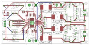
The caps as fitted were all 2.2uf even though as you say the board silk screens say 1.0uf!
I only replaced the two + caps with some 2.2uf JFX polyprops from JB capacitors.
I'd do the other two - caps if there was enough room for them.
Most of the components on the board are different values to what is actually printed on the board!
I suppose next to do is change out the output filter caps with some genuine polys.
But for now it's playing fine.
cheers for that gjf
im gonna get a bigger case and mount the minus inputs under the board to get them in there🙂.
im doing it bit by bit,but as you say the output side of things will certainly need a tweak🙂
does anyone know the value of the standard inductors...im using 8 ohm speakers...am i correct that my inductors need to be 22uf for such a load?
all the best
smithie
Whats the better choice between tpa3116 breeze 2.0 or tpa3118 smsl sa-36a pro?
.
.
Last edited:
regarding breeze and 36a pro,i think the first thing you should ask is how much power do you need,because of the wide ranging power input and heatsink on the breeze your gonna be able to get alittle more wattage out of it if thats crucial to you.
i have no dealings regarding the 36a pro,but smsl stuff is usually put together well,and looking at the photos of it that certainly seems to be the case.
but i like the breeze board to work on if your going to tweak it,it seems a good quality board even if the components on it arent up to much,as for the sound,in standard form,i found it abit rough around the edges but exciting and fun to listen to with good detail and bass extension,to me it seemed alittle lacking in mid bass presence....but these sort of amps can sound so different depending on speakers and systems there played in.....just my 2p view of course😀
regards
smithie
The 36a pro has a significant turn off "pop" noise.
Maybe some do but mine is silent on switch on and off and sounds pretty good too.
Oh thats good to hear. That makes for a far more enjoyable amp. I used to cringe when i had to power mine off.
Maybe some do but mine is silent on switch on and off and sounds pretty good too.
on the yellow breeze board
was there any consensus on what would be a good replacement capacitor for the gvdd cap(one of the five caps squeezed between the wimas and heat sink)
in another note i replaced the smd caps that feed the pvcc decoupling on both sides with some oscons 330uf caps....anyone else found that to be a negitive effect,or is that just me😀
regards
smithie

on the yellow breeze board
was there any consensus on what would be a good replacement capacitor for the gvdd cap(one of the five caps squeezed between the wimas and heat sink)
in another note i replaced the smd caps that feed the pvcc decoupling on both sides with some oscons 330uf caps....anyone else found that to be a negitive effect,or is that just me😀
regards
smithie
gvdd TI value is restricted to 1uF, if you take TI literally no other value is allowed 😀
you don't replace the small smd ceramic decoupling caps for Oscons, you add Oscons and you can add additional smd ceramics too
Oh thats good to hear. That makes for a far more enjoyable amp. I used to cringe when i had to power mine off.
All 36pro can pop, there isn't a good one or a bad one, all are equal regarding pop. Amount of pop for example differs with volumepot setting, used source, efficiency speakers.
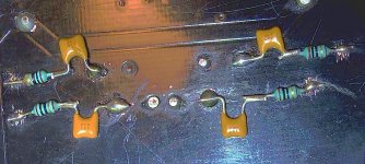
Szerintem valami nem jó, a nyomtatott áramkör lapon a belső 220nF értékű kondenzátor rossz lábára lett forrasztva a snubber kondenzátor. A jó megoldás az, amikor az induktivitás felőli vezető sávra van kötve a 330pF-os kondenzátor !
Last edited:
hi irrlbeo
many thanks for the reply.
many thanks for the reply.
irribeo; you don't replace the small smd ceramic decoupling caps for Oscons said:opps😀
ignorance is bliss🙂
that could explain abit,so i better get some replacements,anyone know what i should put back in there...smd stuff is a total mystery to me,ti application notes are showing 220uf providing im looking at the right caps?,is there a package size or something i need to consider?
a little knowledge is a dangerous thing,but no knowledge is total distruction😀
rergards
smithie
What is the goal of changing caps there - i mean, what are you actually missing or want to improve?
im just a sheep...
have no real skills or knowledge regarding electronics,saw that others had done this mod...minus taking out the original parts😀 so thought i would give it a try for myself as i had those caps lying around and see if i could hear any change in sound,the "marked improvements" that some had quoted....simple as that really.
now due to my mistake ill have a excuse to get some practice in soldering some smd parts in...so a result of sorts😀🙂
all the best
smithie
and on another note,heres a slight variation that i havent seen on here
Breeze Audio GoldenSilver tpa3116 2.0 HiFi digital audio amplifier 50WX2 mini stereo amplifier class d mini hifi audio amplifier-in Amplifier from Consumer Electronics on Aliexpress.com | Alibaba Group
any views,do like the sound of the one i have,although i realise its got issues,just wondered if this iss any better set out??
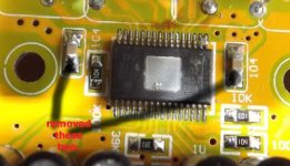
These are normally 10-100nF 50V X7R. From the number shown ("104"), they should be 100nF in this implementation.
104 is meant to 1*10E4 pf == 100nF or 0.1uF
There are several marking-code-tables available over the net, like this:
Elecraft Hands-On Ham Radio
Best way to tell is starting with 2 exactly the same boards and then hear the changes in a (double) blind test, otherwise your expectation will bias the experience. When not driving those boards hard at the upper spec end, there wont be "much/noticeable" difference in whatever sound you looking for.
Having some good input caps (like WIMA/TDK/EPCOS/PANASONIC MKP/MKS/MKT), proper rated inductors and a good power-supply is normally all you need. Speakers and your ears normally produce more distortion than the amp.
But im not into this cap-rolling/audiophile thing.
104 is meant to 1*10E4 pf == 100nF or 0.1uF
There are several marking-code-tables available over the net, like this:
Elecraft Hands-On Ham Radio
.. i would give it a try for myself as i had those caps lying around and see if i could hear any change in sound,the "marked improvements" that some had quoted....simple as that really.
smithie
Best way to tell is starting with 2 exactly the same boards and then hear the changes in a (double) blind test, otherwise your expectation will bias the experience. When not driving those boards hard at the upper spec end, there wont be "much/noticeable" difference in whatever sound you looking for.
Having some good input caps (like WIMA/TDK/EPCOS/PANASONIC MKP/MKS/MKT), proper rated inductors and a good power-supply is normally all you need. Speakers and your ears normally produce more distortion than the amp.
But im not into this cap-rolling/audiophile thing.
Last edited:
- Home
- Amplifiers
- Class D
- TPA3116D2 Amp