Hi Normundss,
Could you please create/share a panel cutout diagram that reflect the latest board?
Thanks,
Fred
Could you please create/share a panel cutout diagram that reflect the latest board?
Thanks,
Fred
At the moment I do not have a drawing with Raspberry Pi cutouts, will add it as soon as I manage to create it.
Great! Thank you!
Nice documentation!
Daniel
Normundus,
thank you for the great documentation.
I am not sure if this was asked before but I have not seen a serial port for communication with DAM board. Since your board connects to the DAM, is there a serial connector on your board?
Thank you
AR2
thank you for the great documentation.
I am not sure if this was asked before but I have not seen a serial port for communication with DAM board. Since your board connects to the DAM, is there a serial connector on your board?
Thank you
AR2
The isolated serial lines from DAM are connected to Raspberry Pi serial port. So if RPi is not used, serial port can be accessed on RPi connector. See the doc for pinout table. There are 1k current limiting resistors in series with RPi the serial lines.
In addition, the DAM J3 connector is fully replicated on the input board. Serial lines can be accessed there as well. This connector is wired directly to DAM without resistors.
In addition, the DAM J3 connector is fully replicated on the input board. Serial lines can be accessed there as well. This connector is wired directly to DAM without resistors.
The isolated serial lines from DAM are connected to Raspberry Pi serial port. So if RPi is not used, serial port can be accessed on RPi connector. See the doc for pinout table. There are 1k current limiting resistors in series with RPi the serial lines.
In addition, the DAM J3 connector is fully replicated on the input board. Serial lines can be accessed there as well. This connector is wired directly to DAM without resistors.
Thank you, that sounds good. I will be using Amanero.
Here is the current status of the boards.
The PCB manufacturer had mixed up the order and made an older test version of the input boards. They are now redoing the order with correct boards, but it is likely to add another week to the schedule.
The switch and the muting boards are good and are currently being assembled. For those who had ordered only the muting board, it will be shipped during this week.
The input boards are likely to be ready at the end of next week.
Those few orders that had only the muting board have been shipped. You should receive a notification from Paypal with the tracking number.
As for the others, I am still waiting for the correct input board PCBs from the manufacturer.
As for the others, I am still waiting for the correct input board PCBs from the manufacturer.
Last edited:
The correct PCBs have finally arrived and are being assembled. I hope to be able to start shipping them out sometime next week.
Thank you, everyone, for the patience.
The orders have started shipping today. The boards are being tested and packed, and will continue shipping out in batches over the next several days.
You will receive a tracking number notification from Paypal on the day your order is shipped.
The orders have started shipping today. The boards are being tested and packed, and will continue shipping out in batches over the next several days.
You will receive a tracking number notification from Paypal on the day your order is shipped.
I received mine yesterday, looks very well made.
A question: What is the correct size/height of the pcb standoffs for mounting an USB module (diyinhk in my case) and for mounting the input board to the dam1021? The ones i have on hands seem a wee bit too short.
A question: What is the correct size/height of the pcb standoffs for mounting an USB module (diyinhk in my case) and for mounting the input board to the dam1021? The ones i have on hands seem a wee bit too short.
Thats the problem with having 10mm metric standoffs and imperial measured connectors. If you can obtain 12mm standoffs, they should work well. For my own build, I use regular 10mm standoffs and put some M3 washers underneath to raise the height a bit.
See here: http://www.diyaudio.com/forums/attachment.php?attachmentid=471149&d=1426117448
See here: http://www.diyaudio.com/forums/attachment.php?attachmentid=471149&d=1426117448
I received mine yesterday, looks very well made.
A question: What is the correct size/height of the pcb standoffs for mounting an USB module (diyinhk in my case) and for mounting the input board to the dam1021? The ones i have on hands seem a wee bit too short.
I received mine yesterday aswell. Looks nice. I'll try it when I build custom enclosure for DAM.
All the paid orders are now shipped. If you have not received an email with a tracking number, please contact me by PM.
Donations have been made to diyaudio.com and to Paul at moredamfilters.info. Thanks for your great work in helping make this DAC better!
I have a few boards left, and more can be made if there is interest. Send me a PM if you want one (or more 🙂)
Donations have been made to diyaudio.com and to Paul at moredamfilters.info. Thanks for your great work in helping make this DAC better!
I have a few boards left, and more can be made if there is interest. Send me a PM if you want one (or more 🙂)
What's limiting the maximum input voltage for the input board's supply? Why 9V maximum? What will fry when I supply 12V DC?
Edit: Also, would it be somewhat beneficial to replace the LM7803 with a lower noise LT1963-3.3 regulator?
Edit: Also, would it be somewhat beneficial to replace the LM7803 with a lower noise LT1963-3.3 regulator?
Last edited:
What's limiting the maximum input voltage for the input board's supply? Why 9V maximum? What will fry when I supply 12V DC?
Edit: Also, would it be somewhat beneficial to replace the LM7803 with a lower noise LT1963-3.3 regulator?
The input voltage is limited by thermal considerations. If you power Raspberry Pi from the same supply, going over 9V input voltage will overheat the 7805 regulator. The board has provisions for adding a heatsink (see the BOM for part number), but with a 12V input, I suspect the power dissipation will be too much even with a heatsink.
However, if you are not powering Raspberry, Arduino or other external devices from the 5V output, 12V input may be fine. Try it and see if the
7805 regulator does not become excessively hot. The next biggest power consumer is DIYINHK USB interface. If you are not using that either, 12V will definitely be fine.
The absolute maximum input voltage, thermal issues notwithstanding, is 20V DC.
The 7805 is working as a pre-regulator for the "dirty" digital supplies, so I don't see any benefits in using a quieter device. Its 5V output is used to power:
1) Raspberry Pi, which has its own onboard regulators
2) 3.3V supply for the input board itself and for the USB interface. The 3.3V is provided by a MCP1703A regulator.
3) If muting board is used, it can power the relay there.
If you want to get really fancy, the documentation linked from the first post of this thread describes how to use your own 5V and/or 3.3V supplies.
Last edited:
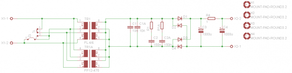
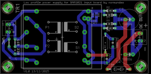
Power supply PCB for the input board
Here is a power supply PCB I put together for the 7V supply. It is intended to fit in a low profile 1U case, so the transformer choices are limited. It will accept Block FL4/6, FL6/6 and FL8/6, as well as Triad FP12-475 transformers. 115/230 V input voltage is configurable by installing wire jumpers.
It will accomodate optional transformer snubbers using SMD or through hole parts.
I will order a batch of 10 pieces from one of the Chinese manufacturers, and can sell the extras on a first come, first serve basis. When they are gone, they are gone. Feel free to order your own PCBs from the included gerbers. The board size is 50mm x 100mm. It is not tested yet, so may contain errors.
Attachments
Thanks for putting the power supply together. Bummer it wasn't available a little sooner. I would have purchased it along with my 3 board kit. I'm in the US and haven't received my boards yet - I know it will take a couple of more days.
People had been waiting for the input boards for several months, so I did not want to delay the GB for another month or so. That is the minimum time to do a PCB for a proper group buy.
This PCB uses low profile transformers, which are relatively expensive, so it may not be to everyones liking.
Anyway, I should have a few extra PCBs sometime in January. Don't know the costs yet, but if you need more than one, you will probably be better off ordering a batch directly.
This PCB uses low profile transformers, which are relatively expensive, so it may not be to everyones liking.
Anyway, I should have a few extra PCBs sometime in January. Don't know the costs yet, but if you need more than one, you will probably be better off ordering a batch directly.
- Home
- Group Buys
- Input and switch boards for Soekris DAM1021 DAC