Ok that's goodI used ceramic insulation and heat transfer paste..
Set both pots to midpoint.
And slowly turn each pot 1 turn at a time while monitoring dc offset and bias.
You should have 2 multimeters hooked up while doing this. One measuring dc offset the other one measuring voltage across source resistors.
Then report back
And slowly turn each pot 1 turn at a time while monitoring dc offset and bias.
You should have 2 multimeters hooked up while doing this. One measuring dc offset the other one measuring voltage across source resistors.
Then report back
Your notice woke me up and checked ceramic insulations. And i saw that its broken cause of very hard pressure. I think, there was a little contact. now everythings okey for one channel. Next i ll try for other channel.I don't see any insulation between mosfet case and heatsink.
That could be a bloody big problem if the heatsinks aren't isolated.
Thanks you very very much.[emoji120]
SM-P602 cihazımdan Tapatalk kullanılarak gönderildi
Your notice woke me up and checked ceramic insulations. And i saw that its broken cause of very hard pressure. I think, there was a little contact. now everythings okey for one channel. Next i ll try for other channel.
Thanks you very very much.[emoji120]
SM-P602 cihazımdan Tapatalk kullanılarak gönderildi
Good work
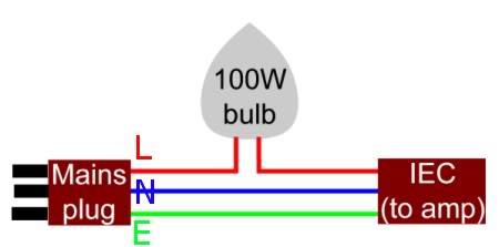
Lightbulb Mains lead notes -
.
In Australia the Live and Neutral pins are the other way around.
https://www.accesscomms.com.au/Reference/powerplug.htm
diyAudio Mosfet F6 BOM (bill of materials) Notes --
Transformer 300-400VA 18+18Vac secondaries, shielded if available. Antek AS-3218 or equivalent (Bigger is useable if you have it, but 300-400VA is about perfect.)
Hi. Beautiful project !
I see you mentioned that transformer, I also see it's really cheap to buy. I wonder how difference would it make if I used custom built local ones as mono blocks. The difference in price would be 200$ more, but will it make much difference ? I mean does it worth it or the cheap Antek will be good enough ? I'm also building a chipamp so same question applies...
Thanks !
mono block config is always better (within same case or two solo)
if nothing else** , green is bigger

**stereo separation absolute , power reserve bigger
if nothing else** , green is bigger
**stereo separation absolute , power reserve bigger
mono block config is always better (within same case or two solo)
if nothing else** , green is bigger
**stereo separation absolute , power reserve bigger
ZM with monoblock config in same case I would think that the grounds from both channels would have to be connected at one point. Or is there a smarter solution?
Thanks. Nash
each audio gnd connected to chassis through CL60 (NTC)
so , they're (channel gnds' separated by two NTCs')
so , they're (channel gnds' separated by two NTCs')
each audio gnd connected to chassis through CL60 (NTC)
so , they're (channel gnds' separated by two NTCs')
Thanks. Understood perfectly.
Nash
I must be getting close, because my Digikey orders are getting smaller: $38.57, $18.06, $7.31, and now (finally?) $0.66. Should a person at least glance at the circuit board before ordering parts? (Asking for a friend.)
R4 goes up in smoke and little V- current draw:
Hi! I built boards and while waiting for splitter transformers just substituted the secondary windings with 47R resistors. Hooking up the board to two lab supplies it was easy to bias and null offset. Now I put in the transformers (Lundahl 1547) and on one of the boards the negative supply draws very little current and R4 started smoking.
I checked the transformer wiring and see no mistake. Who has a hint what to look for?
I checked the transformer wiring and see no mistake. Who has a hint what to look for?
Are you sure the secondary windings have the right phasing?
With primary winding detached it works. The input transistors Q3 and Q4 are not mixed up.
One of the input buffer transistors may be bad, can you try another pair?
Also, you could feed the primary directly with a low impedance source, without the buffer.
Last edited:
Silly Newby question: Is the Full BOM in post 3#
Are the various 'improvements' in the 18 pages summarised anywhere?
Or is it Clever to read/memorise Everything posted?
Really don't want to Bungle anything.. if possible
Are the various 'improvements' in the 18 pages summarised anywhere?
Or is it Clever to read/memorise Everything posted?
Really don't want to Bungle anything.. if possible
Last edited:
One of the input buffer transistors may be bad, can you try another pair?
Also, you could feed the primary directly with a low impedance source, without the buffer.
Hi rayma, I got it figured out, it was a power supply problem.
Thanks!
Small panic attack 😱 I have ordered/paid for the F6 Boards & Tx package.
And the matched Jfets package:
Matched JFET pairs (Grade B) - Parts
Now I'm wondering if these are actually For the F6 build??
Photo sure doesn't look like ones that are bolted to the Heatsink.
Help?
And the matched Jfets package:
Matched JFET pairs (Grade B) - Parts
Now I'm wondering if these are actually For the F6 build??
Photo sure doesn't look like ones that are bolted to the Heatsink.
Help?
- Home
- Amplifiers
- Pass Labs
- F6 Illustrated Build Guide