Yes, Ampliwire is a series of front-ends, and Slewmaster is an excellent option for the power section (OPS).
Ok. Assuming the total amp is a voltage source and a voltage-to-voltage converter then you have the problem to convert voltage to current otherwise it is not a voltage source. BJT is a current controlled device . With Mosfets the problem is not much easier as it is to charge the nonlinear gate drain capacity .
Ole tubes is different as they are charge controlled and the passive output transformer does the job.
The possibly best amp with BJT is a current to current converter as a current source.
Hi Valery,
Can the 2SK117 be used instead of 5089?
Hi RSK,
jFETs 2SK117 will work fine here without any other changes.
Note - if you use some existing PCBs, designed for 2N5089, don't forget to turn 2SK117 180 degrees. In this case the pins will fit just fine 😉
Cheers,
Valery
Ok. Assuming the total amp is a voltage source and a voltage-to-voltage converter then you have the problem to convert voltage to current otherwise it is not a voltage source. BJT is a current controlled device . With Mosfets the problem is not much easier as it is to charge the nonlinear gate drain capacity .
Ole tubes is different as they are charge controlled and the passive output transformer does the job.
The possibly best amp with BJT is a current to current converter as a current source.
Well... if you look deeper into it, you will see that BJT is also a voltage controlled device. Its output current depends on the input voltage (not input current).
MOSFETs are also different from each other. HexFet ones - as you say - have got rather high non-linear input capacitance. But if you drive them from a well-designed emitter follower - you don't care.
Lateral FETs - capacitance is much lower and it's pretty linear - you can drive them directly from VAS.
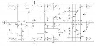
So, in order to have a full amplifier, you need to connect a front-end (giving you all the voltage gain) to a unity gain buffer (giving you all the current gain). One of the good options (EF + HexFETs) is shown in the attachment. With +/-70-75V rails it will give you up to 250W of high-quality power at 8 ohm load.
The other one - mini Slew - is shown earlier in this thread. 100% BJT one will also work perfectly - original Slewmaster by Ostripper is a good example. If you use some other EF3-based BJT output section - just make sure an additional pole, appearing in this case, is properly addressed in order to avoid overall stability issues.
Cheers,
Valery
Attachments
Well... if you look deeper into it, you will see that BJT is also a voltage controlled device. Its output current depends on the input voltage (not input current).
MOSFETs are also different from each other. HexFet ones - as you say - have got rather high non-linear input capacitance. But if you drive them from a well-designed emitter follower - you don't care.
Lateral FETs - capacitance is much lower and it's pretty linear - you can drive them directly from VAS.
So, in order to have a full amplifier, you need to connect a front-end (giving you all the voltage gain) to a unity gain buffer (giving you all the current gain). One of the good options (EF + HexFETs) is shown in the attachment. With +/-70-75V rails it will give you up to 250W of high-quality power at 8 ohm load.
The other one - mini Slew - is shown earlier in this thread. 100% BJT one will also work perfectly - original Slewmaster by Ostripper is a good example. If you use some other EF3-based BJT output section - just make sure an additional pole, appearing in this case, is properly addressed in order to avoid overall stability issues.
Cheers,
Valery
That schematic might turn into a complete single board amplifier channel.😎
Post303
Can you add identifiers where crossing traces are linked? To differentiate from crossing traces that are not linked !
Can you add identifiers where crossing traces are linked? To differentiate from crossing traces that are not linked !
Post303
Can you add identifiers where crossing traces are linked? To differentiate from crossing traces that are not linked !
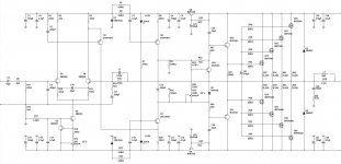
Andrew, I hope, this one looks better.
Jeff - it's from Multisim, presenting it even worth than Diptrace does 😀
Yes, it can be a good single-board amplifier 😎
Cheers,
Valery
Attachments
Does the schematic get easier to view if you print it to a pdf with Foxit? It does a nice job on Diptrace schematics.
Hi RSK,
jFETs 2SK117 will work fine here without any other changes.
Note - if you use some existing PCBs, designed for 2N5089, don't forget to turn 2SK117 180 degrees. In this case the pins will fit just fine 😉
Cheers,
Valery
Thank you Valery,
Very kind of you.
Regards,
Raj
Does the schematic get easier to view if you print it to a pdf with Foxit? It does a nice job on Diptrace schematics.
That's what I did - printed to PDF, enlarged and made a screenshot 😀
Well... if you look deeper into it, you will see that BJT is also a voltage controlled device. Its output current depends on the input voltage (not input current)./That is not correct see for ex. Physics of Semiconductor Devices. BJT are current multipliers. But that is academic. One can current-drive BJTs as well as voltage drive, voltage drive is - naturally- faster as the base-emitter charge after turn-off of the drive voltage is shorted by the zero impedance of the voltage source. But current drive is very linear.
So the problem with the BJT OPS connected to ampliwire frontend is the compensation - which may be designed in a Spice model.
Hopefully.
That's what I did - printed to PDF, enlarged and made a screenshot 😀
What happening here?😕😕😕😀
Jeff, it is something wrong in this zip file.The silkscreen pdf isn't so useful.I fixed up the silkscreen around some connectors.
Please have a look.
Silkscreen?Jeff, it is something wrong in this zip file.The silkscreen pdf isn't so useful.
Please have a look.
Where?
There is no pdf nor zip in the last 36posts.
post307 shows a jpeg, 1817 pixels wide.
Last edited:
Jeff, it is something wrong in this zip file.The silkscreen pdf isn't so useful.
Please have a look.
Do you need it un-mirrored?
Yes Jeff,this is what i mean.Do you need it un-mirrored?
The components view pdf is mirrored.
Yes Jeff,this is what i mean.
The components view pdf is mirrored.
Here it is.
Attachments
Apparently marrying frontend with some BJT OPS is not an easy affair. I do not have the Spice models for the BJTs of the schematic so ...but i do not think that is a big problem.
I never simulate with real load but always with a proven model of a simple two way speaker with passive crossover. Proven means the complex impedance vs frequency of the real device is matched very well by its simulation.
Why not redesign the frontend as a "discrete Opamp?".
I never simulate with real load but always with a proven model of a simple two way speaker with passive crossover. Proven means the complex impedance vs frequency of the real device is matched very well by its simulation.
Why not redesign the frontend as a "discrete Opamp?".
Apparently marrying frontend with some BJT OPS is not an easy affair. I do not have the Spice models for the BJTs of the schematic so ...but i do not think that is a big problem.
I never simulate with real load but always with a proven model of a simple two way speaker with passive crossover. Proven means the complex impedance vs frequency of the real device is matched very well by its simulation.
Why not redesign the frontend as a "discrete Opamp?".
Hi friend,
Pehaps you would be int6in reading through the Slewmaster thread and see just how many different IPS sections were happily married to the the 3ef BJT OPS. I would certainly not call it a tough affair. If will make you happy I will gladly hook any of these IPS up to my Slewmaster 5 pair BJT OPS and post some sine and square waves.
Blessings, Terry
- Home
- Amplifiers
- Solid State
- Revisiting some "old" ideas from 1970's - IPS, OPS