Hi Tolik,
I assume that you expect the analyzer to have a distortion, which is at least 10dB better than the DUT. If so, I think that measuring 0.0005% should be possible. At least for the one unit that exists so far. The statistics is a bit weak at the moment 🙂
Yes, the board uses the LME49990 in several places. The output drivers (in combination with LME49600), the input stage (in combination with LSK389) and the ADC driver stage.
I don't have an answer to the last question. I haven't even calculated the component cost at the moment. Let alone the cost including manufacturing. There are many variables to consider. But once the design gets close to the final version and the functionality has been verified, I will try to make a rough estimate.
@googlyone
I am not quite sure I understand the sentence "Might be easier and better going for a "good but not so simple" approach".
If I end up with a design using separate boards for ADC (+ ADC drivers) and DAC (+ output filters) the analog interfaces will be fully differential.
I am not quite sure I understand the sentence "Might be easier and better going for a "good but not so simple" approach".
If I end up with a design using separate boards for ADC (+ ADC drivers) and DAC (+ output filters) the analog interfaces will be fully differential.
Jens:
Once you split it into an ADC and a DAC it may be easier to use SPDIF I/O for each. You get isolation and a simple packaged I/O chip and module that would be easy to deploy. I know SPDIF has bad connotations here but it really works. All the measurements I have made of the AK4490 were through the AK4115 and the jitter was nonexistant. The ADC side doesn't care. Maybe the minidsp goes from the spdif to a USB interface for the PC?
Once you split it into an ADC and a DAC it may be easier to use SPDIF I/O for each. You get isolation and a simple packaged I/O chip and module that would be easy to deploy. I know SPDIF has bad connotations here but it really works. All the measurements I have made of the AK4490 were through the AK4115 and the jitter was nonexistant. The ADC side doesn't care. Maybe the minidsp goes from the spdif to a USB interface for the PC?
How would you handle clock distribution if you split the DAC and ADC onto separate boards though? ASRC on DAC side? I have been tinkering with a project like this myself and the issue I come up with is it seems like a bad idea to put the clock on a different board than the ADC since that's the most critical converter for the most part. If you want to use them synchronously you'll have to feed the clock to the DAC board also.
My thought was to put ADC and DAC on one board with 2 separate boards, one for the ADC input stuff and one for the DAC output. It would have to be a short run over a quality connector though.
Demian:
SPDIF is sort of nice because you can use optical for real isolation, but the it seems the parts that Toshiba sold that worked at 192kHz are discontinued? I guess you can use coax with a pulse transformer, though. I'd rather use CM6631A or XMOS but you run into two different issues. For C-Media you'll need to sign an NDA and hope they respond to you to get the firmware framework. With XMOS you have to pay for a working UAC2 Windows driver.
Do you like AK4115 more than the WM880x parts?
Chris:
With SPDIF the clock in the ADC becomes the master clock, at least when its used to drive everything. There is no requirement that both ends run the same clock. When I'm testing some systems the analog source clock may be completely different (e.g. Bluetooth) and all I care about is the analog out. What is important is very good clocking on the ADC, which I think has been handled.
If you use an EMU 1212m or Juli@ setup on a pc you can lock everything to the SPDIF input. There is no reason for a local clock for the DAC. Maybe the miniDSP can be configured this way.
I have not tested the Wolfson chip so I can't really comment. I know the AKM chips are very good. I'm not sure of the status of those parts now that Wolfson is part of Cirrus.
It seems the 192 capable toslink stuff is still around somewhere. I have received new stuff that is 192 capable in optical. Toslink would be great. Make the ADC and DAC modules battery powered and you can use long Toslink cable so the sensitive parts are well away from the host PC. It opens a host of possibilities.
Thank you for doing the 20kHz measurements, these results are also very good.
The first curve in the PDF illustrates nicely the tradeoff between SNR and THD@0dBFS. Delta-sigma converters all have increasing THD with higher amplitudes so there is a tradeoff on which voltage level to put the 0dBFS point.
Between 0dBFS and -5dBFS the distortion decreases 10dB. Between -5dBFS and -12dBFS the distortion decreases by another 10dB. So it seems to me that "your 0dBFS" should be somewhere between -5dBFS and -12dBFS.
Why does the 94.777kHz tone only show up in the noise measurements and not in the distortion measurements? What did change between the two measurements?
The 94.777kHz tone seems to be some kind of idle noise spurious. A similar tone is visible in figure 26, page 28 in the AK4490 Evaluation Board Manual. This is for a sample rate of 44.1 kHz. It is not visible in the figure for 192kHz sample rate (figure 43), but that figure only shows up to 80kHz!
The Ak4490 does generate some spurious at the upper end of the frequency range. They change with the input level. Not ideal, but hopefully still acceptable.
The Ak4490 does generate some spurious at the upper end of the frequency range. They change with the input level. Not ideal, but hopefully still acceptable.
Jens,
The point of "Might be easier and better going for a "good but not so simple" approach" is exactly that.
- if you use separate boards for the ADC and DAC, then without fully differential inputs and outputs you will be killed by noise between the two different grounds (by this I mean that the ground on the ADC and DAC will have noise on it comprising digital hash and also signal related noise).
- In my mins single ended measurements will be limited to the -110 dBc region with such an approach.
- In a system integrating the ADC and DAC into a low impedance common ground, then you can avoid (a fair bit of) the problems that separate daughtercards will see between their grounds.
- A balance between the complexity of a fully differential system, and a larger more complex single PCB will need to be addressed.
- A fully isolated system is an option as noted above. Again, this increases complexity.
Jens,
- if you use separate boards for the ADC and DAC, then without fully differential inputs and outputs you will be killed by noise between the two different grounds
Or, at least one of them (ADC or DAC) should have isolated power and I2S digital isolation to avoid the ground loop (that's what I'm doing).
Last edited:
It might be doable to make it behave more like one ground plane with a very low impedance connection between boards. A high density board to board connector with a lot of pins dedicated to ground and ensuring there is at least one ground pin adjacent to a signal should help.
Chris,
I have done a motherboard and daughterboard approach for ADC and DACs. This uses 26 way IDC connectors, and ribbon cable, with every second line on the IDC cable being ground. This does OK, but still introduces measurable "issues" between the ADC and DAC boards if used single ended.
For normal use in my crossover, which is where this gear all started it's life, this is not relevant. The effects are well below any meaningful level, but in a piece of test gear it is a real limiting factor.
The use of a balanced input to the ADC should help - this is ready for integration and test now.
As a second test, I am tempted to try "stitching" a DAC and ADC board together along one edge, which should "tie" these planes together nicely.
@googlyone
Thanks for the explanation.
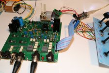
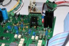
The design is fully differential, so I think it will be possible to move the ADC and the DAC to separate boards without too much trouble. I have attached a couple of pictures, which show the present test setup. Notice the AK5394A board, which is mounted vertically. The analog signals and a couply of ground connections are mounted on the edge closest to the main PCB. The I2S, power supply and a few control signals are connected at the top, most of them through a flat cable, where each of the critical signals (I2S and MCLK) have a ground wire running in parallel.
Not exactly an ideal mounting method, but all the measurements using the AK5394A that I have shown previously were made using this setup.
You can also see the heat sink, which, with vertical mounting, is sufficient to improve the distortion considerably.
@altor,
Isolating e.g. the DAC and output circuits has been discussed before. I agree that for some use cases this would be preferable. I won't completely rule it out at this point in time, but it will complicate the design and introduce new risks. I think that with the balanced input a lot of ground noise problems can be eliminated. So it may not be needed in most cases.
@1audio
One of my goals from the outset was that it should be possible to use it with virtually any PC, including portable PC's. Using SPDIF would make this difficult. USB is almost always available. It must be a good USB port though, not one that has gone through a USB hub.
@chris719
Even if I move the ADC and DAC to separate boards they will still share the same master clock, which comes from the main board. Except for the addition of a couple of connectors, the clock system would be the same. Of course I have to be careful with the master clock routing, but I think it can be handled.
Thanks for the explanation.
The design is fully differential, so I think it will be possible to move the ADC and the DAC to separate boards without too much trouble. I have attached a couple of pictures, which show the present test setup. Notice the AK5394A board, which is mounted vertically. The analog signals and a couply of ground connections are mounted on the edge closest to the main PCB. The I2S, power supply and a few control signals are connected at the top, most of them through a flat cable, where each of the critical signals (I2S and MCLK) have a ground wire running in parallel.
Not exactly an ideal mounting method, but all the measurements using the AK5394A that I have shown previously were made using this setup.
You can also see the heat sink, which, with vertical mounting, is sufficient to improve the distortion considerably.
@altor,
Isolating e.g. the DAC and output circuits has been discussed before. I agree that for some use cases this would be preferable. I won't completely rule it out at this point in time, but it will complicate the design and introduce new risks. I think that with the balanced input a lot of ground noise problems can be eliminated. So it may not be needed in most cases.
@1audio
One of my goals from the outset was that it should be possible to use it with virtually any PC, including portable PC's. Using SPDIF would make this difficult. USB is almost always available. It must be a good USB port though, not one that has gone through a USB hub.
@chris719
Even if I move the ADC and DAC to separate boards they will still share the same master clock, which comes from the main board. Except for the addition of a couple of connectors, the clock system would be the same. Of course I have to be careful with the master clock routing, but I think it can be handled.
Attachments
Also see QA401 about to be released soon.....note their choice of ADC:
QA405 and QA401 Status - QuantAsylum
THx-RNMarsh
QA405 and QA401 Status - QuantAsylum
THx-RNMarsh
Also see QA401 about to be released soon.....note their choice of ADC:
By the way, I have one question - looking an the QA400 photoes, specification table, etc. and I do not see any regulation signs - no UL, no CE, no FCC, no ENxxxx, etc. - i.e. EMI/FRI (EMC) and Safety Regulations.
OK, UL may be not relevant is the device is not powered from mains, but what about EMC?
The same thing - looking at Berkeley's DAC: Alpha DAC Series 2 ? Berkeley Audio Design
It is a mains powered, but there is no UL sign at the back panel!
Also about EMC -nothing!
It is clear, that for many people, especially radio amateurs, all UL/FCC/CE is not a big deal 🙂, device's price&performance are more important, but how is possible to sell the electronic devices in US without UL/FCC?
Maybe somebody, who is familiar in US/EU regulations, is able to explain this?
Many small companies do not sell enough to warrent the expense of UL testing. And, it is required in USA but it is in other countries. If you dont want to risk being sued for any damages caused by the product.... you get it UL approved.
Another way is to use all UL approved parts and practices for that type product but not go thru the verifying/tested at UL.
THx-RNMarsh
Another way is to use all UL approved parts and practices for that type product but not go thru the verifying/tested at UL.
THx-RNMarsh
UL is not required in the US. A few cities do but its mostly ignored as a regulation. CE is required for EU importation but a single product will slide in without no problem.
FCC and its local equivalents are a different story. If QA sells in the US they do need FCC since they are in the US. Buts that's pretty cheap. What gets pricy is a radio for use in many countries with $2-3K per country. However personal import usually walks around those issues.
High end audio usually ignores this stuff since the volume is tiny and its all under the radar. Importers are on the hook for their countries.
Sent from my Nexus 5 using Tapatalk
UL is not required in the US.
Sent from my Nexus 5 using Tapatalk
This is correct... I tried to add the missing word Not but the system had timed out on me. Thanks.
THx-RNMarsh
And, it is NOT required in USA but it is in other countries.
Another way is to use all UL approved parts and practices for that type product but not go thru the verifying/tested at UL.
THx-RNMarsh
- Home
- Design & Build
- Equipment & Tools
- DIY Audio Analyzer with AK5397/AK5394A and AK4490