for subjective comparisons you might make a quick K-tube - maybe of rolled up paper, 1"ID and around 5.3" long to try on the 250 clone - elevate it ~20 to 30 degrees above horizontal

It seems like that has the potential to work as a waveguide with wide horizontal bandwidth and narrow vertical bandwidth. (Which is what we want, or at least that seems to be the path I'm headed down.)
Problem is diffraction; with no baffle it's going to have a lot.
Baffling that K-tube would probably help reduce that, but it would be tricky to build. (Wish I was faster with Blender*!)
* blender.org - Home of the Blender project - Free and Open 3D creation software
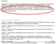
I checked the paper Patrick cites too. In the first picture we see first normalized directivity graphs of a conventional 2-way and Beolab 5. The lowest is not-normalized and we see on-axis and power response of Beolab.
In the other copy-paste we see their conclusion - B5 interacts with a room better than average because of it's different dispersion - wall reflections "style"
We can question that conclusion - at least I do! Omnis live on early reflections and the wall material (it's reflective properties) play a markable role. Also, with lots of reflections we usually get a "spacious" but not "accurate" spatial imaging of a stereo recording. I do have a pair of omni speakers, so this is not just theoretisizing!
By the way, the original is an active speaker with ICEPower D-class amps and automatic room EQ by dsp! http://www.bang-olufsen.com/en/sound/loudspeakers/beolab-5
Attachments

Last edited:
I find it interesting, that Patrick's measurements show so much radiation backwards, behind the reflector. I must say, that after doing many up to 180¤ measurements, I am not surprized by that! 2-3kHz soundwaves are lurky!
I find it interesting, that Patrick's measurements show so much radiation backwards, behind the reflector. I must say, that after doing many up to 180¤ measurements, I am not surprized by that! 2-3kHz soundwaves are lurky!
I was quite surprised that there was so much rejection to the back, particularly at 1-2khz. The level *behind* the speaker was down by approximately 15dB.
With such a small baffle, I'd expected that it would basically be omni at that octave, since 1500hz is 9" long and the baffle was only 5".
While experimenting with the platters yesterday, I think I may have found a clue. I noticed that the speaker had a 180 degree pattern, even with just the reflector!

^^ Picture this, but with the top platter absent.
I'll upload some measurements with my hypothesis on how this is working.
This afternoon I've been doing some experiments with spiral horns. The reason for this is to vary the expansion ratio of the horn. (I believe that the parallel walls of the radial horns that I've been building is leading to comb filtering; breaking up the parallelism spreads out the resonances, and should make the dips in the comb filtering less severe.)
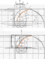
While looking at a Fibonacci spiral, it occured to me that each segment should reflect the sound into the next segment at 90s degrees.
IE, a Fibonacci spiral may have good high frequency output, because each segement 'reflects' into the next.
So it's possible that a Fibonacci spiral may have superior high frequency response to other spiral expansions.
While looking at it, it occurred to me that the shape looks familiar...
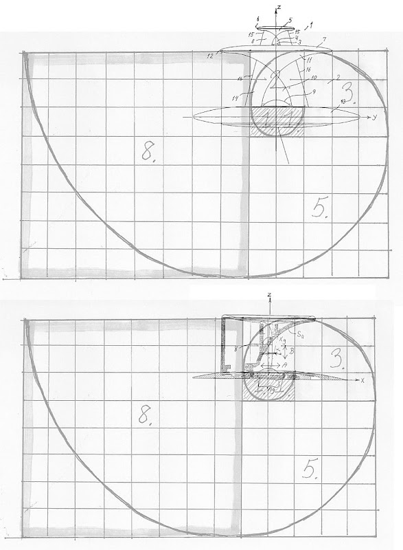
Ha! The SAW lens is a Fibonacci spiral, with the driver at the apex.
(pics from the Sausalito Audio Works patent.)
While looking at a Fibonacci spiral, it occured to me that each segment should reflect the sound into the next segment at 90s degrees.
IE, a Fibonacci spiral may have good high frequency output, because each segement 'reflects' into the next.
So it's possible that a Fibonacci spiral may have superior high frequency response to other spiral expansions.
While looking at it, it occurred to me that the shape looks familiar...
Ha! The SAW lens is a Fibonacci spiral, with the driver at the apex.
(pics from the Sausalito Audio Works patent.)
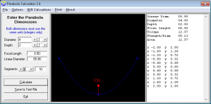
What does a parabolic waveguide do?
Using the ripple simulation applet from Falstad:
Ripple Tank Simulation
I see a number of effects that would guide the designer to use small platters relative to the wavelength.
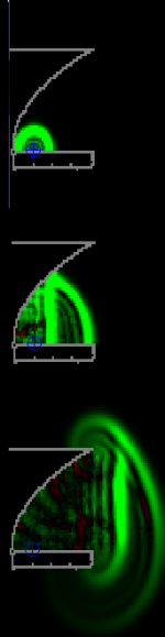
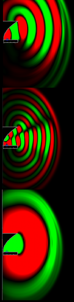
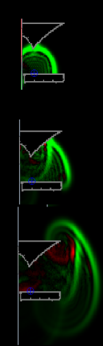
Firstly the wavefront radiates spherically until it contacts the waveguide. It then reflects and converts to a straight / cylindrical? wavefront. Two wavefronts exit the waveguide which is a distortion which might be measured as group delay ?
Secondly the wavefront reaches the platter edge and creates a diffractive wave. this seems stronger at the top in the lateral directions where the guide is more open at the base?
Thirdly the waveguide has an acoustic structure that forms a low pass filter with a cut off near where the opening is close to one (or is it half?) a wavelength.
The directivity of the driver would mean that the waveguide would only be called on to redirect the wave off the driver axis at the higher end of its range so presumably the actual dimensions of the parabola and platter are key characteristics determined by the driver diameter and the crossover frequency?
Note: The app can generate a parabola and it is close to the display edge so I only generated half the guide.
Using the ripple simulation applet from Falstad:
Ripple Tank Simulation
I see a number of effects that would guide the designer to use small platters relative to the wavelength.
Firstly the wavefront radiates spherically until it contacts the waveguide. It then reflects and converts to a straight / cylindrical? wavefront. Two wavefronts exit the waveguide which is a distortion which might be measured as group delay ?
Secondly the wavefront reaches the platter edge and creates a diffractive wave. this seems stronger at the top in the lateral directions where the guide is more open at the base?
Thirdly the waveguide has an acoustic structure that forms a low pass filter with a cut off near where the opening is close to one (or is it half?) a wavelength.
The directivity of the driver would mean that the waveguide would only be called on to redirect the wave off the driver axis at the higher end of its range so presumably the actual dimensions of the parabola and platter are key characteristics determined by the driver diameter and the crossover frequency?
Note: The app can generate a parabola and it is close to the display edge so I only generated half the guide.
Attachments
Last edited:

I've built a BUNCH of these. I wouldn't be surprised to find that I've built more than the inventor has. (When they invented this years ago, 3D printing wasn't readily available. Now that it is, it enabled me to try a zillion different variations.)
Arguably, this was the most successful shape. It's the lens from Sausaliton Audio Works, merged into a JBL progressive transition waveguide.
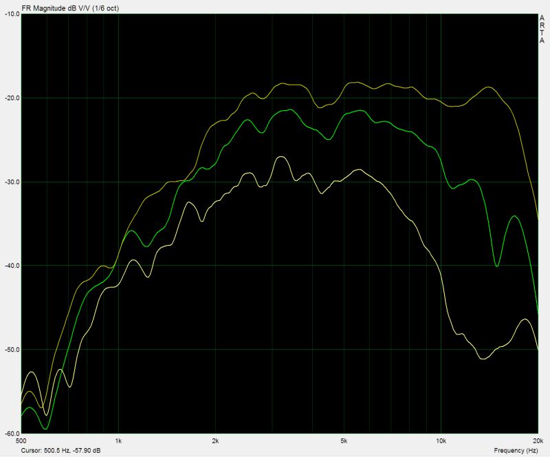
Here's the polars. They're not as smooth as the best waveguides I've measured, but they're close. The advantage of this contraption is that it can be used with a $25 tweeter, and the tweeter can me mounted straight up. The one that I printed was also a small fraction of the size of the big waveguides that perform well.
Which begs the question, if I'd scaled it up to a large size, would it perform better? I'm inclined to say "yes"
* The rectangular QSC waveguide is the smoothest I've measured. But it also requires a compression driver and it's much larger. All told, the cost is about quadruple.
Arguably, this was the most successful shape. It's the lens from Sausaliton Audio Works, merged into a JBL progressive transition waveguide.
Here's the polars. They're not as smooth as the best waveguides I've measured, but they're close. The advantage of this contraption is that it can be used with a $25 tweeter, and the tweeter can me mounted straight up. The one that I printed was also a small fraction of the size of the big waveguides that perform well.
Which begs the question, if I'd scaled it up to a large size, would it perform better? I'm inclined to say "yes"
* The rectangular QSC waveguide is the smoothest I've measured. But it also requires a compression driver and it's much larger. All told, the cost is about quadruple.
If anyone out there wants to build these, here's a short summary of what worked for me, and what didn't.
1) Whatever you do, do NOT use a large tweeter. I couldn't get acceptable results from a 29mm tweeter. A 19mm tweeter worked great. I think what's happening here is that the energy which would normally be beaming is spread out instead. IE, if you had a tweeter which played to 20khz on a flat baffle, but was beaming, it will NOT play to 20khz on a Sausalito Audio Works lens because the energy which was formerly focused into a beam is not spread out into a cone. So the overall output is wider, but the intensity level is lower. The net effect is that it's very very hard to get a 29mm dome to play to 20khz on a SAW lens.
2) Theoretically, the height of the bullet shaped part of the lens should determine the vertical coverage. In reality, I didn't notice any real difference. The authors of the patent have filed a new patent, and in the new patent the height of the "bullet" is much shorter.
3) I found that it's important that you can draw a straight line from the microphone to the dome of the tweeter. IE, if you have any type of obstruction in the way, the diffraction from that edge wrecks the response entirely. One way to verify this in person is to simply look at the device, and if you can see the dome peeking out, it will perform well. If there's ANYTHING in the way, forget about getting flat response at all. I found this out the hard way when I made one of these devices that fed a horn:
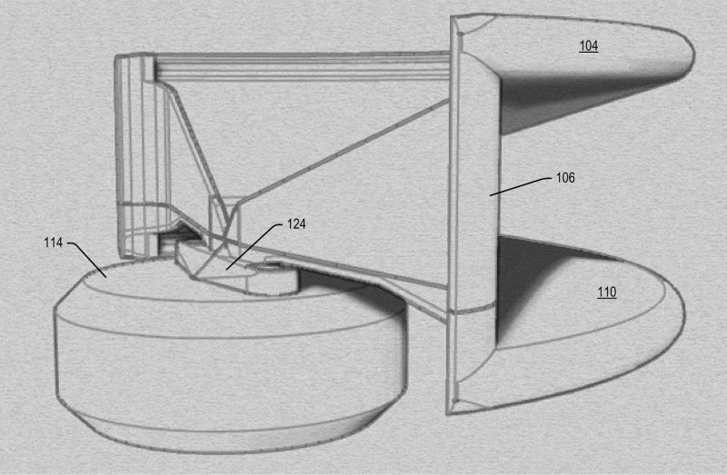

Mine looked a lot like this device from the new patent, but my device had a more pronounced "lip" around the tweeter. And I believe that lip wrecked the polars.
Again, I've probably made about twenty of these now, so I have a decent idea of what works with these lenses. 75% of the ones I built were failures 🙁
1) Whatever you do, do NOT use a large tweeter. I couldn't get acceptable results from a 29mm tweeter. A 19mm tweeter worked great. I think what's happening here is that the energy which would normally be beaming is spread out instead. IE, if you had a tweeter which played to 20khz on a flat baffle, but was beaming, it will NOT play to 20khz on a Sausalito Audio Works lens because the energy which was formerly focused into a beam is not spread out into a cone. So the overall output is wider, but the intensity level is lower. The net effect is that it's very very hard to get a 29mm dome to play to 20khz on a SAW lens.
2) Theoretically, the height of the bullet shaped part of the lens should determine the vertical coverage. In reality, I didn't notice any real difference. The authors of the patent have filed a new patent, and in the new patent the height of the "bullet" is much shorter.
3) I found that it's important that you can draw a straight line from the microphone to the dome of the tweeter. IE, if you have any type of obstruction in the way, the diffraction from that edge wrecks the response entirely. One way to verify this in person is to simply look at the device, and if you can see the dome peeking out, it will perform well. If there's ANYTHING in the way, forget about getting flat response at all. I found this out the hard way when I made one of these devices that fed a horn:
Mine looked a lot like this device from the new patent, but my device had a more pronounced "lip" around the tweeter. And I believe that lip wrecked the polars.
Again, I've probably made about twenty of these now, so I have a decent idea of what works with these lenses. 75% of the ones I built were failures 🙁
Patrick, do you happen to have a 3D model of the lens or detailed drawings with dimensions? I want to try and print it to work with dunaudio esotar 110 speakers?
I've been reading your posts about Fibonacci spiral, but my geometry isn't that good, so I can't order 3D model anywhere without knowing dimensions.
I've been reading your posts about Fibonacci spiral, but my geometry isn't that good, so I can't order 3D model anywhere without knowing dimensions.
Patrick, do you happen to have a 3D model of the lens or detailed drawings with dimensions? I want to try and print it to work with dunaudio esotar 110 speakers?
I've been reading your posts about Fibonacci spiral, but my geometry isn't that good, so I can't order 3D model anywhere without knowing dimensions.
Which one?
Go figure - the inventor of the Beolab lens has worked on a number of well known albums.
Neat.
Manny Lacarrubba | Credits | AllMusic
Neat.
Manny Lacarrubba | Credits | AllMusic
Am I right thinking that you can just scale the 3D model to get same results for midrange dome speaker?
Level Confusion ...
... in the Hierarchy of Acoustic Terminology; e.g.:
a) All waveguides, are baffles but not all baffles are waveguides.
b) All horns are waveguides but not all waveguides are horns.
WHG
So a flat baffle is a waveguide? Than all loudspeakers have been waveguides forever? An expansion of the definition of a waveguide that now includes everything that has ever been made or ever will be made. Marketing will love that. 🙂
... in the Hierarchy of Acoustic Terminology; e.g.:
a) All waveguides, are baffles but not all baffles are waveguides.
b) All horns are waveguides but not all waveguides are horns.
WHG
Am I right thinking that you can just scale the 3D model to get same results for midrange dome speaker?
Correct.
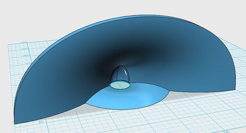
The bullet shaped thing in the waveguide is only there to do two things:
First, it concentrates the output of the driver into a point.
Then it bends it ninety degrees.
So the waveguide behaves as if it's being driven by a source that's small.
- Status
- Not open for further replies.
- Home
- Loudspeakers
- Multi-Way
- Cloning a $3200 Speaker for $400