Before I located the HLMP-6000 part, I had pretty decent luck with Kingbright.Thanks. Known brand.
If we ignore the harmonic spray in your test rig (...)
This buggers me for several days now. How can I get rid of it? With the preamp connected but unpowered the spectrum looks pretty clean, with only a small bump of ~5dBV at mains frequency. From what I've read so far it's probably common mode noise being picked up and amplified by the preamp, and I've found only two 'solutions' for this problem so far. Either put a common mode choke in front of the preamp, or use a differential amplifier (instrumentation amp) instead of my simple preamp.
Since I can't test any of the two on-the-fly due to lack of components, I'd like to ask you for some advice first. Does a common mode choke make sense at all? I'd have to put one of the coils into the GND line, which is problematic due to the BNC socket being connected to the metal case... Will an in-amp make a decent preamp? Noise performance might be a little worse out of the box (but nothing that can't be come by with enough effort and money), but if it keeps the mains noise out I'd be happy.
Bcarso and Jack are much more specialized to help you on this. Me thinks best is to go with the balanced input instrumentation op-amp plan housed in a "shielded" metal container like a cookies can, powered by batteries so to have nothing to do with the mains, and skip the other ways.
If it is truly common-mode, a decent choke will not affect the differential signal of interest. But I agree with Salas that a good instrumentation amp and battery power is best. And that performance can be spoiled with too-large loop areas.
Really good differential sensing is a source of additional frustration, as one is not merely doubling the component count in the front end, but needing to double the parts in each input to preserve the same noise performance for voltage noise. In doing so one is increasing the current noise, which in this case with low source impedances (e.g. measuring regulator noise) is no big deal, but for other applications it can be a problem.
This is partly why some designers so favor JFETs for the front end, as out of the gate (npi) the current noise generators are small at audio frequencies.
Brad
Thanks for the input. Been thinking about building a differential preamp with either an AD8428 or a 'discrete' one with three LT1115 (as 3x LT1028 would be too expensive for my taste already) and power it with a Dual Salas instead of batteries, but with the transformer housed in a different case (like I did with my current preamp). Never running out of things to build...
Thanks for the input. Been thinking about building a differential preamp with either an AD8428 or a 'discrete' one with three LT1115 (as 3x LT1028 would be too expensive for my taste already) and power it with a Dual Salas instead of batteries, but with the transformer housed in a different case (like I did with my current preamp). Never running out of things to build...
As you know, distance is your friend when it comes to magnetic fields, falling off with distance by about the third power until one is very far away, at low frequencies. That is, one is always in the EM near field for feasible distances (this did Tesla in, despite his brilliance). Toroidal transformers are nice for many things, but the topology is imperfect when you bring out lead wires, or wind them nonuniformly.
When I did a hybrid tube-transistor active crossover for a friend, he insisted on using some very large copper foil-paper-oil output coupling capacitors. They were in proximity in a single steel chassis to a large toroid. The result was audible hum, and it could be almost nulled by moving the toroid a bit --- but this required a bigger box. It would have been far better to have accepted the need for a two-box system from the beginning.
About the op amps: remember that with substantial gain in the first two-amp stage for the standard inamp configuration, the third four-resistor internal diff amp doesn't have to be the same type or nearly so low noise. And of course keep impedances as low as possible in that first two-amp section, limited by the current drive capabilities of those first two amps. Also, since you will be looking at small signals in the main, that first-section voltage swing can be fairly small. You could also use discrete buffers which are more complex but cheap to enhance the ability to drive the low-Z gain-determining resistors.
Something like this? Gain will be 60dB in the first stage. Bandwidth should be sufficient (~60kHz -3dB); else I'd have to go for something like 40dB + 20dB. The gain setting resistor is pretty low with 2x 1R in parallel, so I might already need a file for trimming it 😎. The right halve of the circuit would be comprised of a single 5532, which should be good enough with typical 5nV/sqrt(Hz) and hard to beat on price vs. performance.
Attachments
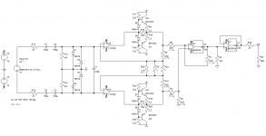
That looks good, although you could go lower noise by losing those 47 ohm input resistors.Something like this? Gain will be 60dB in the first stage. Bandwidth should be sufficient (~60kHz -3dB); else I'd have to go for something like 40dB + 20dB. The gain setting resistor is pretty low with 2x 1R in parallel, so I might already need a file for trimming it 😎. The right halve of the circuit would be comprised of a single 5532, which should be good enough with typical 5nV/sqrt(Hz) and hard to beat on price vs. performance.
Hi Lasse,
Isn't there any way to get away from so many 0.1% resistors with maybe a couple trims? Using resistors in the multiple per SIP packages would get you some matched and thermally tracking parts for example. That's if the part to part match is more important than the precise value.
-Chris
Isn't there any way to get away from so many 0.1% resistors with maybe a couple trims? Using resistors in the multiple per SIP packages would get you some matched and thermally tracking parts for example. That's if the part to part match is more important than the precise value.
-Chris
From what I've read, every imbalance of those resistors translates into a much worse CMRR. That's why they get laser trimmed in integrated solutions like the aforementioned AD8428 and easily cost 20 bucks apiece. I don't know what's more important in this case, 1% vs 0.1% for precision or integrated vs single resistors for temperature tracking. And I don't know if those resistors can be trimmed with a file while watching the spectrum on the PC for lowest common mode noise. Things I'll have to find out...
Those 47R at the inputs are there to limit the coupling cap charge current somewhat. I've omitted that for my current preamp, so maybe I can get away without them here, too.
Those 47R at the inputs are there to limit the coupling cap charge current somewhat. I've omitted that for my current preamp, so maybe I can get away without them here, too.
Linear Tech makes some matched quad resistor arrays that might be appropriate. Not ridiculously expensive.
4x 1k is as low as it gets; 2x 1k + 2x 9k seems to be the only part in stock and single quantities cost more than a LT1028...
Edit: Found something from Vishay in 4x 500R and 4x 100R; they're just as expensive but SMD only with like 10mW max for a single resistor, which precludes the use of higher currents. Seems like a monte carlo sim is the next thing to do.
Edit: Found something from Vishay in 4x 500R and 4x 100R; they're just as expensive but SMD only with like 10mW max for a single resistor, which precludes the use of higher currents. Seems like a monte carlo sim is the next thing to do.
Last edited:
Anybody care to check whether that simulation is correct? 😱
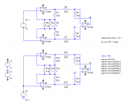
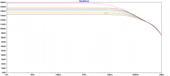
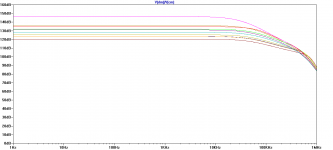
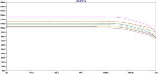
Monte-Carlo'ed six resistors in ten runs for different precisions of 0.025% (LT parts), 0.1% and 1%. This was just for the resistor values, not for temperature. Note that every single resistor has a different random number in its tolerance range, they're not all six of the same value in each run.
Monte-Carlo'ed six resistors in ten runs for different precisions of 0.025% (LT parts), 0.1% and 1%. This was just for the resistor values, not for temperature. Note that every single resistor has a different random number in its tolerance range, they're not all six of the same value in each run.
Attachments
Why did you choose R13/14 as 10k?Something like this? Gain will be 60dB in the first stage. Bandwidth should be sufficient (~60kHz -3dB); else I'd have to go for something like 40dB + 20dB. The gain setting resistor is pretty low with 2x 1R in parallel, so I might already need a file for trimming it 😎. The right halve of the circuit would be comprised of a single 5532, which should be good enough with typical 5nV/sqrt(Hz) and hard to beat on price vs. performance.
W.Jung tells us to use very high in trying to approach the >10M of a transformer. I seem to remember he suggested 1M5
Hi Lasse,
Isn't there any way to get away from so many 0.1% resistors with maybe a couple trims? Using resistors in the multiple per SIP packages would get you some matched and thermally tracking parts for example. That's if the part to part match is more important than the precise value.
-Chris
From what I've read, every imbalance of those resistors translates into a much worse CMRR. That's why they get laser trimmed in integrated solutions like the aforementioned AD8428 and easily cost 20 bucks apiece. I don't know what's more important in this case, 1% vs 0.1% for precision or integrated vs single resistors for temperature tracking. And I don't know if those resistors can be trimmed with a file while watching the spectrum on the PC for lowest common mode noise. Things I'll have to find out...
Those 47R at the inputs are there to limit the coupling cap charge current somewhat. I've omitted that for my current preamp, so maybe I can get away without them here, too.
one can match to ~0.1% with a 2000 count DMM.Linear Tech makes some matched quad resistor arrays that might be appropriate. Not ridiculously expensive.
If one has a 20000 count DMM, then with care one can get to 0.02% (1 part in 5000 = +-2 parts in 20000) matching at no cost other than time.
Last edited:
the worst case -100dB for the +-1% surprises me. Whitlock talks much lower CMMR in his articles.Anybody care to check whether that simulation is correct? 😱
Monte-Carlo'ed six resistors in ten runs for different precisions of 0.025% (LT parts), 0.1% and 1%. This was just for the resistor values, not for temperature. Note that every single resistor has a different random number in its tolerance range, they're not all six of the same value in each run.
Is your 1% actually +-0.5%?
Why did you choose R13/14 as 10k?
W.Jung tells us to use very high in trying to approach the >10M of a transformer. I seem to remember he suggested 1M5
I headed for something that gives a reasonably low rolloff with the input caps, assuming that lower resistance means lower noise here.
the worst case -100dB for the +-1% surprises me. Whitlock talks much lower CMMR in his articles.
Is your 1% actually +-0.5%?
Where can I find those articles?
My 1% sim is in the range of 465.344 to 474.697 for 470R and 469.534 to 470.47 for the 0.1% setting.
W.Jung has his own web site.
He has dozens of articles in there.
Whitlock has hundreds of articles, some are in Jensen's website, but they have made it more awkward to use.
Google will find many, try the links that are not Jensen.
He has dozens of articles in there.
Whitlock has hundreds of articles, some are in Jensen's website, but they have made it more awkward to use.
Google will find many, try the links that are not Jensen.
After you connect the Source, then the 10k has no effect on noise, it is paralleled with the Source output impedance, ~10r to 1k0I headed for something that gives a reasonably low rolloff with the input caps, assuming that lower resistance means lower noise here.
Last edited:
- Status
- Not open for further replies.
- Home
- Amplifiers
- Power Supplies
- The simplistic Salas low voltage shunt regulator