Discovered that my RCA grounding was poor. I soldered all the ground tabs to the nut to get proper contact, now it sounds great!
I'm relaxing with a beer listening to music through my diy system and realize I never experienced such great sound before using semi-expensive commercial gear.
This forum is the best thing that happened to my hobby.
Thanks for a great design and kit Salas. 🙂
I'm relaxing with a beer listening to music through my diy system and realize I never experienced such great sound before using semi-expensive commercial gear.
This forum is the best thing that happened to my hobby.
Thanks for a great design and kit Salas. 🙂
 You are welcome. Enjoy.
P.S. A hint by the way. For treating metal contacts of switches and plugs, also good for cleaning rotary pots, get a can of Cramolin Contaclean in Europe. Its the same well respected old Cramolin R5 reddish formula. For those in USA there is the slightly altered Deoxit D5 to get. Shipping such flammable spray stuff over air is not allowed, so better look for national dealers.
I don't think Cramolin have any dealers In Norway, is it better then crc contact cleaner?
I'm planning on building some kind of dac, can the power supply drive a dac and the buffer at the same time?
I'm planning on building some kind of dac, can the power supply drive a dac and the buffer at the same time?
Yes it can. Someone used DCB1 as PSU and buffer for his Soekris recently with good results. Take into account the dac's max current demand and make sure the CCS setting is enough of course.
Cramolin is best. Ask at branch INTERFLUX NORGE AS
Contact
Cramolin is best. Ask at branch INTERFLUX NORGE AS
Contact
There should be some surface shipping alternative within Europe. You can deoxidise and protect tubes pins also by working them in & out of a socket a few times after spraying that stuff.😉
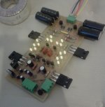
Just finished to assembly my DCB1.
PSU section says 10.16V and 10.08V as output voltages, is it good enough?
Anything else I'd better to measure?
Have to finish the buffer stage to know the DC offset...
PSU section says 10.16V and 10.08V as output voltages, is it good enough?
Anything else I'd better to measure?
Have to finish the buffer stage to know the DC offset...
Your PSU section readings are acceptable. Measure the voltage drop across each big current setting resistor to see if the current is within 10% between sides. Divide that Vdrop by the value of the resistor. Answers the current through each.
Have 2 buffers wonder if I can use a LM 49600 as extra buffer after the fets and a feedback loop?
Current seems to be ok: 0,0626 vs 0,0594 that means a 5% difference.
IRF9240 and 240 closer to the rectifiers are pretty warm, I can take my fingers on them but they are definitely hotter than the other two.
Final voltages are stable at 10.21 va 10.15 that means a 0,5% difference.
PS: I love yellow leds used here 🙂
IRF9240 and 240 closer to the rectifiers are pretty warm, I can take my fingers on them but they are definitely hotter than the other two.
Final voltages are stable at 10.21 va 10.15 that means a 0,5% difference.
PS: I love yellow leds used here 🙂
Attachments
Is there a problem with DCB1 transient performance? What is the extra buffer buying you in this scenario?
Is there a problem with DCB1 transient performance? What is the extra buffer buying you in this scenario?
You are to no help.
Current seems to be ok: 0,0626 vs 0,0594 that means a 5% difference.
IRF9240 and 240 closer to the rectifiers are pretty warm, I can take my fingers on them but they are definitely hotter than the other two.
Final voltages are stable at 10.21 va 10.15 that means a 0,5% difference.
PS: I love yellow leds used here 🙂
All readings OK on this home etched guy. You could use small individual sinks for the warmer MOSFETS. They are big devices that can support a bit of extra weight. Those two are having more than 10V across that the output ones have if the transformer is 15-0-15VAC
P.S. Watch your power on/down system sequence as I see no relay in your build. What are those extra TO-220s for? Some post step down regulators for another circuit?
Have 2 buffers wonder if I can use a LM 49600 as extra buffer after the fets and a feedback loop?
If you lack current drive in some certain system, its one of the many ways one could think so to boost current. Doable.
Me concept wise I would try to solve this while keeping the simplistic theme of DCB1. Say use same circuit but DN2540s for K170s. They should run at 120-130mA. One should watch source components impedance and new higher Ciss. DC offset could be a problem but one output coupling capacitor is still hundreds less silicon junctions and not yet another feedback scheme as it would be with adding IC. JFETS are still quieter and nicer than MOSFETS but eeh, we now got a strongman DCMOS1 🙂
- Home
- Source & Line
- Analog Line Level
- Salas hotrodded blue DCB1 build