A pair of JBL 2240's, have come up locally, at a similar price to the faitals. Million dollar question are these vintage drivers better sonically for HiFi use. BTW- they have fresh cones on them.
Lewinskih01 noticed that Beyma changed/improved the 12P80Nd for 2015, and this new version seems better suited for use with the TPL-150H @1600Hz Xover. Beyma has a press release for the 12P89Nd.v2 which states the improvements support smoother SPL needed for higher frequency crossovers.
Thread
http://www.diyaudio.com/forums/multi-way/274194-new-beyma-12p80nd-v2.html#post4324158
Picture
http://www.diyaudio.com/forums/atta...6d1431468842-new-beyma-12p80nd-v2-12p80nd.jpg
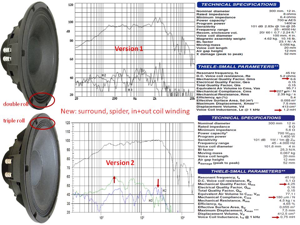
GUESS at: Beyma 12P80Nd changes between version1 vs. version2
New cone surround. Best way to tell V1 vs. V2
1) cone surround: old = double roll(M-roll); new = triple roll
New stiffer suspension spider.
2) Mechanical Compliance(surround + spider): old Cms = 227 um/N; new Cms = 180 um/N
New inside+outside windings on voice coil former
3) Le inductance: old = 1.2mH; new = 0.75mH
4) Bl: old = 23.1; new = 25.3
---V1 cone breakup between 1.6KHz - 3KHz has been removed in V2
---V2 looks like excellent partner for the TPL-150H with LR4@1.6Khz
---V2 has higher distortion 200Hz-500Hz, but lower distortion 2KHz-3KHz
============
JBL 2240 are great woofers, BUT purchasing an old speaker which had enough heavy use to need new cones has risks.... might need a quick impedance vs. freq plot to confirm that they are near-spec. (PC w/amp sweeps freq as good-DVM measures voltage across a 10 ohm 1% series resistance)
Measuring Loudspeaker Driver Parameters
For BIG woofer surrounds--
The best sounding drivers have most of the restoring force in the spider, and very little in the surround.
For each application, absolute truth is in the details for each speaker design and materials.
Personally, for 15" and 18" woofers(Fs<32Hz):
I favor treated+coated 3-roll accordian edge surround for Xmax up to 10mm. This woofer tech sounds "consistent" when blended with most midbass I use, and has good transient response.
I favor treated foam surrounds for 10mm-16mm Xmax. This tech sounds "linear" over low->high SPLs, has good transient response, low distortion, and good efficiency.
Thread
http://www.diyaudio.com/forums/multi-way/274194-new-beyma-12p80nd-v2.html#post4324158
Picture
http://www.diyaudio.com/forums/atta...6d1431468842-new-beyma-12p80nd-v2-12p80nd.jpg
GUESS at: Beyma 12P80Nd changes between version1 vs. version2
New cone surround. Best way to tell V1 vs. V2
1) cone surround: old = double roll(M-roll); new = triple roll
New stiffer suspension spider.
2) Mechanical Compliance(surround + spider): old Cms = 227 um/N; new Cms = 180 um/N
New inside+outside windings on voice coil former
3) Le inductance: old = 1.2mH; new = 0.75mH
4) Bl: old = 23.1; new = 25.3
---V1 cone breakup between 1.6KHz - 3KHz has been removed in V2
---V2 looks like excellent partner for the TPL-150H with LR4@1.6Khz
---V2 has higher distortion 200Hz-500Hz, but lower distortion 2KHz-3KHz
============
JBL 2240 are great woofers, BUT purchasing an old speaker which had enough heavy use to need new cones has risks.... might need a quick impedance vs. freq plot to confirm that they are near-spec. (PC w/amp sweeps freq as good-DVM measures voltage across a 10 ohm 1% series resistance)
Measuring Loudspeaker Driver Parameters
For BIG woofer surrounds--
The best sounding drivers have most of the restoring force in the spider, and very little in the surround.
For each application, absolute truth is in the details for each speaker design and materials.
Personally, for 15" and 18" woofers(Fs<32Hz):
I favor treated+coated 3-roll accordian edge surround for Xmax up to 10mm. This woofer tech sounds "consistent" when blended with most midbass I use, and has good transient response.
I favor treated foam surrounds for 10mm-16mm Xmax. This tech sounds "linear" over low->high SPLs, has good transient response, low distortion, and good efficiency.
You voice my concerns over the reconed drivers, the baskets were originally from 2245's so the surrounds may have perished.
As in the sealed cabinet the compliance is going to be dominated by the air in the cabinet, i was wondering whether a TL arrangement would be better. For the midrange a TTL (terminated) would be quite easy to implement, 6 foot tapering line, stiffening the cabinet as well. Should be able to achieve it in the same volume as for straight forward sealed box.
Now the real challenge would be a TTL for the subwoofer, easy enough to design, in a big cabinet, unlikely to be able to achieve the it for an 18" driver in a 150 ltr cabinet which i can do for sealed.
Did some modelling of TTL's using MJK's software, tried to replicate the B&W Nautilus tapered tubes, without a conclusion, as there seems to be to many variables to play with. It seems that the B&W taper tubes start @ about 1SD, which goes against recommended practice, of 2*SD for a straight line and 4*SD for tapered lines. I need to read some more on transmission lines, and try and understand if you are not interested in bass extension, can over stuffing reduce the length/volume of the lines.
I have modelled for the Beyma 12" a TTL for a 2.5sd:0 tapered line 70" long. Similar results in MJK's and the Leonard audios software. The SPL profile tracks what i would expect from a sealed box, with a few ripples of nodes, which are fixed with stuffing. I am right in assuming i won't see any benefit, in any of these simulations over a sealed baffle, with the only benefit being no reflected back wave?
I modelled the line the size, to be about 80 ltrs slightly smaller than the sealed box size i was considering.
Should be able to fold this length of line into a 50cm (d) x 45cm (W) x70cm (h) box which will include the TPL and 12" driver.
Sanity - check - is what i am doing sensible, have tried exploring the corners of the envelope, longer lines, more tapered etc. Doesn't seem to affect the SPL, phase or delay responses significantly.
I have modelled for the Beyma 12" a TTL for a 2.5sd:0 tapered line 70" long. Similar results in MJK's and the Leonard audios software. The SPL profile tracks what i would expect from a sealed box, with a few ripples of nodes, which are fixed with stuffing. I am right in assuming i won't see any benefit, in any of these simulations over a sealed baffle, with the only benefit being no reflected back wave?
I modelled the line the size, to be about 80 ltrs slightly smaller than the sealed box size i was considering.
Should be able to fold this length of line into a 50cm (d) x 45cm (W) x70cm (h) box which will include the TPL and 12" driver.
Sanity - check - is what i am doing sensible, have tried exploring the corners of the envelope, longer lines, more tapered etc. Doesn't seem to affect the SPL, phase or delay responses significantly.
Hi. I'm following this as I purchased the TPL and one option under consideration is the 12P80Nd to go with it. I'm surprised by the size of the sealed box you are considering. On UniBox, 80 liters returns a Qtc of 0.2. I thought Qtc that low sounded anemic, but maybe I'm wrong and can learn something. Would you mind ellaborating?
I was hoping line source my have elaborated the logic, as he is more eloquent than me. As far as I understand its all about getting the response curve decay as shallow as possible and using a dsp to flatten it. The big box should have less compression of the air, as the drivers response is improved. When I have built then, I will know if its true, my query of using the TTL is to have been less colouration, hopefully getting open baffle qualities without the compromise's.
I was hoping line source my have elaborated the logic, as he is more eloquent than me. As far as I understand its all about getting the response curve decay as shallow as possible and using a dsp to flatten it. The big box should have less compression of the air, as the drivers response is improved. When I have built then, I will know if its true, my query of using the TTL is to have been less colouration, hopefully getting open baffle qualities without the compromise's.
I was hoping line source my have elaborated the logic, as he is more eloquent than me. As far as I understand its all about getting the response curve decay as shallow as possible and using a dsp to flatten it. The big box should have less compression of the air, as the drivers response is improved. When I have built then, I will know if its true, my query of using the TTL is to have been less colouration, hopefully getting open baffle qualities without the compromise's.
Let me see if loading this screen shot works. It's my ppsl using Eminence Definimax 4012HO in what might be considered waaaay too large of an enclosure,
say for example, 2 cubic feet each driver, as opposed to the optimum (?) 1.2
Lean, mean, dynamic, punchy; walks all over what an open baffle ever dreamnt of doing. Response well into the 30's despite what the "predictors" might say.
Darn it, file will not load (too large) !!
But it spec'd out at" Fc 53.16, Qtc .579 Le .836
(Sealed system)
The bottom line result is, this over sized enclosure with a shallow roll off blends extremely well with the sub woofer system used at 60 and below.
Also.... I agree that Mr. LineSource can explain this better.
Here is my thoughts for the TTL for the beyma. Going for the same volume as i would for a sealed cabinet giving a qtc of 0.22. which i estimate gives me the best compromise on box volume v LF decay, for a sealed cab.
I need to confirm the decay for a TTL using MJK software.
I need to confirm the decay for a TTL using MJK software.
Attachments

Hi Steven,
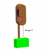
I do not know about the TTL as such, but if you go for this configuration I would have the port for the 12p80nd BELOW the driver in order to have the TPL-150H and the 12p80nd as physically close to each other as possible.
PS: I am very curious to hear about your impressions of the 12p80nd!
Best regards
Peter
Here is my thoughts for the TTL for the beyma. Going for the same volume as i would for a sealed cabinet giving a qtc of 0.22. which i estimate gives me the best compromise on box volume v LF decay, for a sealed cab.
I need to confirm the decay for a TTL using MJK software.
Peter, TTL. Terminated transmission line has no port, (look on the web at B&W Nautilus). I agree getting the two drivers closer together would be better, will look at rearranging the transmission line to as achieve this.
From some modelling yesterday evening, I doesn't look like changing the tapers length's etc of a TTL affects the SPL. I am getting 87db/watt at 100 hz, a big sealed box is similar. Worried that my 8 watt amp may not be powerful enough to drive an equalised signal down to an 80 hz crossover. I need to look at how much power is required for 100db output at 80 hz accounting for the decay slope of the filter.
From some modelling yesterday evening, I doesn't look like changing the tapers length's etc of a TTL affects the SPL. I am getting 87db/watt at 100 hz, a big sealed box is similar. Worried that my 8 watt amp may not be powerful enough to drive an equalised signal down to an 80 hz crossover. I need to look at how much power is required for 100db output at 80 hz accounting for the decay slope of the filter.
Peter, TTL. Terminated transmission line has no port, (look on the web at B&W Nautilus). I agree getting the two drivers closer together would be better, will look at rearranging the transmission line to as achieve this.
From some modelling yesterday evening, I doesn't look like changing the tapers length's etc of a TTL affects the SPL. I am getting 87db/watt at 100 hz, a big sealed box is similar. Worried that my 8 watt amp may not be powerful enough to drive an equalised signal down to an 80 hz crossover. I need to look at how much power is required for 100db output at 80 hz accounting for the decay slope of the filter.
I'm growing intrigued by TTLs. What are the best articles/threads you have come across? I found this here, but doesn't say much. http://www.diyaudio.com/forums/multi-way/108243-closed-end-transmission-line-4.html
Then the Nautilus articles mostly refer to the 800 Nautilus line which only applied TL to the midrange. I can see the TTL in the woofer in Nautilus speaker, but haven't found good articles.
Am I right to understand the benefit is the same transient speed as a sealed enclosure (because it is sealed) plus lack of bounce from the rear wall which then goes out through the driver?
That's my understanding of the benefits of TTL's. What I am trying to understand is there any benefit from the volume and rate of taper of the line, as I am not seeing that much difference in my simulations from a 2x sd compared with 1x sd.
Having read that thread you gave the link for it seems, like it needs to be a 1/2 wave lenght line, and will only cover limited octaves. GM's comments below suggest little benefit from the idea - so back to the simple IB
It is, though as already noted it will have to be end loaded 1/2 wave (AKA plane wave tube (PWT)) to keep from having to excessively stuff it to damp its 1/4 WL resonances.
That said and without any detail technical or hands on knowledge of these drivers, IME it will damp them so well if properly designed that they may only be usable over a relatively narrow BW, requiring either a tweeter or CD horn EQ that will significantly reduce its effective efficiency.
As you increase net Vb to allow it to 'breathe', you quickly revert back to being just a near I.B. loading, so of limited use beyond cosmetic.
GM
Driver arrived, running them in now.
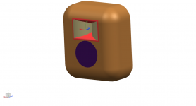
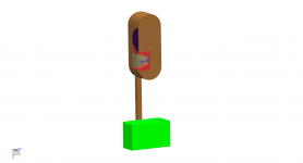
Starting to plan the cabinets now. I like the Grimm LS1 idea so i was thinking i would take inspiration from there approach, inspired by the white paper, will be using my SET amp though.
The image attached are my initial thoughts for the cabinet, flush mounting the TPL and rear mounting the 12" driver to align voice coils. I thought i would go for a 6" radius around the front edges to minimise diffraction. Could continue the radius around the back for asthetics. Propose to use a couple of 3" dia stainless tubes to connect it to an upward facing sub cabinet.
Couple of question/advice.
Crossing at say 1500Hz don't need to get the drivers that close to each other, is there any harm in bringing them as close as i can?
To facilitate bringing the drivers as close as possible, i am rear mounting the 12" driver into a rebated groove, with 1/4" radius around the mouth. Whats the best practice for rear mounting drivers, wrt to the opening in the cabinet?
( I will get some laser cut steel rings to clamp the drivers into the rebate, as insuffient depth to use the driver mounting holes)
Attachments
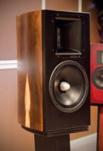
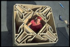
Vapor Audio has several IMPRESSIVE trans-lam cabinets, including the Arcus model using the TPL-150H "close-mounted" to a 10" Lambda TD10M midbass. Worth a look.
--tapered volumes for absorption material
--slots for vibration control sand
--large round-overs for diffraction control
--SOLID & HEAVY
Trams-lam construction is expensive.... laser cut stainless steel does not sound cheap.
--did you get (2015)version 2 of the Beyma 12P80Nd?
--tapered volumes for absorption material
--slots for vibration control sand
--large round-overs for diffraction control
--SOLID & HEAVY
Trams-lam construction is expensive.... laser cut stainless steel does not sound cheap.
--did you get (2015)version 2 of the Beyma 12P80Nd?
Attachments
Not sure what version of the driver i have got, i have been waiting for them to come from Spain for the last 6 weeks, - so hopefully version 2, how would i tell no marking of version on box or driver.
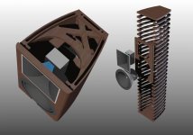
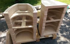
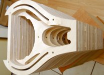
Construction of the cabinets i am happy with, not sure on the materials yet, but i have a profesional understanding of vibration and constrained layer damping. Initally i will make test boxes from birch ply, as i have access 3d cnc machine to form the rounded corners.
The attached pictures hopefully give a better insight into what's in my mind, basically a rip off of the Grimm with bigger drivers. The issues this brings is the height of the setup. I have flipped the driver orientation vertically as rightly or wrongly i throught it was better to have the TPL at seated ear height?
For the subwoofer duty (below 80hz) i was thinking of using a Dayton RSS390HF driver, as its all pistonic motion i liked the idea of a aluminium cone. What i dont know yet is how close i could bring the mid/HF cabinet vertically down before the dispersion of the LF is compromised, i sort of feel that the generous radius on the underside of the cabinet will act as a guide. I had thought it may be an idea to flip the sub driver so it fires into the cabinet, the rear of the cone should give better omnidirectional dispersion. (I know WAF zero - maybe a foam cover)
Constructive advise/critic please - will this be sonically better than just cloning the Daniel Hertz M1 with radiused corners?
Attachments
The cabinet above shouldn't affect the sub below a few hundred Hz. The alternative to radiusing for low frequencies is to ensure continuous expansion room from the cone outward.
Just the challenge in overlapping the contours. A diffraction penalty could easily stack up against lobing.is there any harm in bringing them as close as i can?
Sounds good.To facilitate bringing the drivers as close as possible, i am rear mounting the 12" driver into a rebated groove, with 1/4" radius around the mouth. Whats the best practice for rear mounting drivers, wrt to the opening in the cabinet?
- Status
- Not open for further replies.
- Home
- Loudspeakers
- Multi-Way
- Advise on mid range driver