Not sure what version of the driver i have got, how would i tell no marking of version on box or driver.
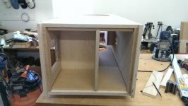
Construction of the cabinets i am happy with, not sure on the materials yet,
... basically a rip off of the Grimm with bigger drivers.
For the subwoofer duty (below 80hz) i was thinking of using a Dayton RSS390HF driver, as its all pistonic motion i liked the idea of a aluminium cone.
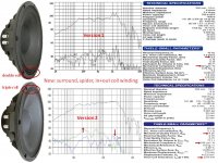
12P80Nd version2 has a 3-roll surround.... version1 has a 2-roll(M-roll) picture attached.
TPL-150H ~100db/watt.
12P80Nd ~95db/watt. Simulations of a sealed box alignment shows ~ 180-200Hz F3.
The Dayton RSS390HF has 87db/watt efficiency from a 283g Mms. A higher efficiency woofer which easily reaches 200Hz would be my choice. As discussed earlier, a pair of 15"-18" woofers is required for 95+db/watt deep bass.
Do you think it would be worth the effort to perform time-alignment measurements(square waves) on the TPL-150H and 12P80Nd before your CAD design? If you plan a passive Xover, you should also run additional delay measurements with a good guess of Xover connected. This data could help others.
Many large speakers use a complex shape, low diffraction front baffle, attached to flat side panels. Gluing MDF sheets onto Plywood sheets measures well for resonance reduction, after good cross-bracing.
Attachments
Hey vinyl. I'm following your thread with attention.
A while back you were looking into a terminated transmission line, for the 12p80Nd I believe. Just wanted to mention I also looked into this - in my case the range was 80-450Hz - and exchanged with some knowledgeable people including Martin J King and came to the same conclusion as you: for frequencies around 80Hz and below, there seem to be only marginal benefits from doing a terminated TL vs a sealed enclosure. The significant benefits seem to emerge when you compare open baffle with open TL.
FWIW, from that research I also concluded I want to try TL for my midrange and tweeter (also a TPL-150H). Have you seen the posts mentioning an improvement in performance of the TPL when the plastic back cover is removed and let breathe into a 1 or 2 liter box?
BTW, in your drawn configuration you probably want to make the legs to the midrange/tweeter unit pretty stiff front-to-back to minimize box movement as a reaction of the 12p80 moving. I would suggest making those legs as wide as possible (vs thickness, which is not so important). The same goes for the way the legs will attach to the upper box and sw box. Plus the sw vibrations will get to the mid/tweeter box thru the legs.
The driver i have been sent are version 1 ones, my supplier is goint to contact Beyma to see why i wasn't sent version 2 ones. Couple of week hiatus as beyma are on factory shut down.
Noticed an interesting cabinet construction on the web, "innerchoic" on PBN speakers see image. I cannot see how to manufacture this without a laser cutter, which i haven't access to, interesting though if it really works. (Closest i can see of replicating this is to spray over egg box foam a pu coating to seal the pores and give a semi-rigid structure.)
http://www.pbnaudio.com/images/stories/INNERCHOIC/SammyCalloutsFNL.jpg
regarding the sub woofer the 18" faital requires 11db more power to drive to 30Hz than the dayton.
yes i know the legs look abit unstable - maybe 3 legs.
The grimm style will only happen if the upward facing sub- has benefit over a forward facing sub. As no one has commented on this approach i assume the benefits are marginal.
Noticed an interesting cabinet construction on the web, "innerchoic" on PBN speakers see image. I cannot see how to manufacture this without a laser cutter, which i haven't access to, interesting though if it really works. (Closest i can see of replicating this is to spray over egg box foam a pu coating to seal the pores and give a semi-rigid structure.)
http://www.pbnaudio.com/images/stories/INNERCHOIC/SammyCalloutsFNL.jpg
Interesting cabinet. What do you think is the purpose of the rear chamber in the picture a the bottom left?
The driver i have been sent are version 1 ones, my supplier is goint to contact Beyma to see why i wasn't sent version 2 ones. Couple of week hiatus as beyma are on factory shut down.
Noticed an interesting cabinet construction on the web, "innerchoic" on PBN speakers see image. I cannot see how to manufacture this without a laser cutter, which i haven't access to, interesting though if it really works. (Closest i can see of replicating this is to spray over egg box foam a pu coating to seal the pores and give a semi-rigid structure.)
http://www.pbnaudio.com/images/stories/INNERCHOIC/SammyCalloutsFNL.jpg
regarding the sub woofer the 18" faital requires 11db more power to drive to 30Hz than the dayton.
yes i know the legs look abit unstable - maybe 3 legs.
The grimm style will only happen if the upward facing sub- has benefit over a forward facing sub. As no one has commented on this approach i assume the benefits are marginal.
The idea looks familiar...

With a bit of work and preparation you can do it: http://www.diyaudio.com/forums/full-range/242171-making-two-towers-25-driver-full-range-line-array.html
As the entire design isn't displayed - perhaps in consideration of "proprietary IP?" , I'm thinking connection of the upper woofer to lower chamber, with perhaps some MLTL action happening? The shallower section in front would be the isolated enclosure volume for the MTM array.
"Pristine" sound chamber, indeed
Nice enough piece of production engineering, but rather inefficient use material - but then I'm just not a big fan of the stacked lamination approach. There are other ways to do curves that aren't as costly in materials - but as they say in the trade CCM
With MDF's average density of 45lb / ft^3, these things have gotta weigh a couple of hundred pounds, No doubt there are configurations at several times that weight, but who wants to move them around to tweak placement, angles, etc.
These things have gotta weigh several hundred pounds
Dayton Audio Xenia
Whilst looking on the PBN website for more details on the cabinet construction i found there DIY section, with an interesting bass configuration. Back to back bass driver pairs but the rear driver is firing into a secondary chamber within the cabinet, can anyone enlighten me on how this is working, could it be firing into a sealed chamber?
Whilst looking on the PBN website for more details on the cabinet construction i found there DIY section, with an interesting bass configuration. Back to back bass driver pairs but the rear driver is firing into a secondary chamber within the cabinet, can anyone enlighten me on how this is working, could it be firing into a sealed chamber?
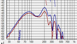
This is the floor firing woofer taken ground plane outside the mouth. The second plot is using damping across the back (taken off the floor). Low end isn't ready. Some crossing.if the upward facing sub- has benefit over a forward facing sub.
There could be slot load style cancellation above 400Hz. The modes are fairly simple, but set fH. This is a 15" with a back and one side. The opening is approximately Sd.
The floor mounting also seems solid.
Attachments
Maybe ported, isobaric 😕can anyone enlighten me on how this is working,
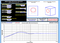
Whilst waiting for the drivers to be corrected, i have started playing with jeff Bagby's diffraction spreadsheet. I have attached a couple of screen shots of my simulations. As i was anticipating going from a sharp edge to a 6" radius improves things, obviously offsetting the driver to one side would also help. Ideally the response would want to be rule straight, can anyone give me a feel of what i need to aim for. the only thing i have been looking at is the off axis response. for both V & H angles the response remains flat past the cross over freq of 1500hz.
Not quite sure what to do with the room boundary reinforcement plots - enlightment please!
Not quite sure what to do with the room boundary reinforcement plots - enlightment please!
Attachments
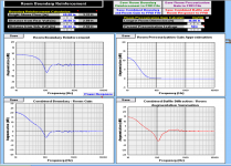
There are a few sources of sound. The first plot is the direct sound, combined with diffracted sound that directs toward the listener minus that which doesn't. This other sound comes back to the listener after interacting with the room.the only thing i have been looking at is the off axis response. for both V & H angles the response remains flat past the cross over freq of 1500hz.
Not quite sure what to do with the room boundary reinforcement plots - enlightment please!
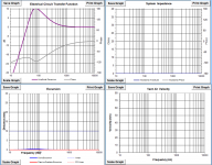
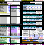
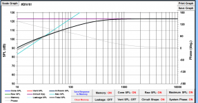
i have been playing with some parameters in the Jeff B's simulation software, for the sealed cabinet for the beyma 12p80nd. Interestingly increasing the cabinet size doesn't seem to lift the response at the crossover point [see fig 1] it does however drop fc. For 50 litres fc=70hz, for 125 litres fc=56hz, i assume as am crossing around 80hz keeping fc as far outside the running range as possible will be best.
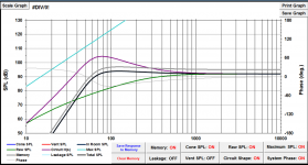
Fig 2 shows my input to the worksheet. Fig 3 shows the proposed DSP input to get a flat response. I show the response @ 4 and 8 watts the later being the max for my dht amp. The levels i think will be fine for my 1500 cubic foot room.
Fig 4 and Fig 5 detail the other outputs from the simulation.
Does it all look sensible, or have i missed something?
Attachments

i have been playing with some parameters in the Jeff B's simulation software, for the sealed cabinet for the beyma 12p80nd. Interestingly increasing the cabinet size doesn't seem to lift the response at the crossover point [see fig 1] it does however drop fc. For 50 litres fc=70hz, for 125 litres fc=56hz, i assume as am crossing around 80hz keeping fc as far outside the running range as possible will be best.
Fig 2 shows my input to the worksheet. Fig 3 shows the proposed DSP input to get a flat response. I show the response @ 4 and 8 watts the later being the max for my dht amp. The levels i think will be fine for my 1500 cubic foot room.
Fig 4 and Fig 5 detail the other outputs from the simulation.
Does it all look sensible, or have i missed something?
I ran the Bagby spreadsheet with your parameters and Qtc is coming out as 0.232. Isn't that so low it would sound "anemic"?
Still waiting for the 12p80nd v2 to be shipped from the factory, hope its worth the wait. For information if you are in the Czech republic, you can get the drivers for around 150 Euros each, but they won't ship out of country.
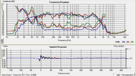
Drivers eventually turned up. Here are a couple of measurements i made "in room" so need to discount room contribution.
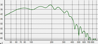
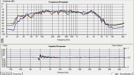
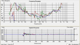
In a seal box of around 140 ltrs, 50% filled with BAF (all i had), LF is contoured with DSP to give a flat response to 80 hz ( ~+10 db low shelf)
Blue trace is at 10cm from dust cone, red trace is 1m away, greem trace is 2.4m away at listening position, traces normalised on SPL. Pretty true to spec sheet accounting for the room.
The distortion in the last picture is a concern if is real, seems to get bigger the further the mic is away from source - so i assume erronous.
Next phase to fill cabinet with concrete block to bring the volume down to 70 ltrs and 50 ltrs to see if my calculations match reality.
Attachments
Drivers eventually turned up. Here are a couple of measurements i made "in room" so need to discount room contribution.
In a seal box of around 140 ltrs, 50% filled with BAF (all i had), LF is contoured with DSP to give a flat response to 80 hz ( ~+10 db low shelf)
Blue trace is at 10cm from dust cone, red trace is 1m away, greem trace is 2.4m away at listening position, traces normalised on SPL. Pretty true to spec sheet accounting for the room.
The distortion in the last picture is a concern if is real, seems to get bigger the further the mic is away from source - so i assume erronous.
Next phase to fill cabinet with concrete block to bring the volume down to 70 ltrs and 50 ltrs to see if my calculations match reality.
Thanks for sharing this. Were you able to listen to music? How did it sound?
Response looks pretty impressive from 80 to 2000 Hz. I guess people aren't crossing it over at 2kHz because of beaming. Would be a natural choice with a TPL, yet folks are xo this combo at around 1.6kHz.
Does your DSP "cut down SPL" only, or are you boosting down low? I ask because I use Acourate for DSP and it will only cut down.
Not had a chance to listen to then in speakers yet, listened to one driver on its own, initially sounded like a poor quality radio, but is improving as iit's being used more.
My aim is to use it with TPL, just got to understand how much of the midrange horn magic i am sacrificing, weighting this up with the better coherence i will have from not having a x-over in the critical 300Hz range.
As far as i know, cutting back is the best approach to defining gain structure with a DSP, which is what i have done.
As far as i know, cutting back is the best approach to defining gain structure with a DSP, which is what i have done.
That is my understanding as well.
Not had a chance to listen to then in speakers yet, listened to one driver on its own, initially sounded like a poor quality radio, but is improving as iit's being used more.
My aim is to use it with TPL, just got to understand how much of the midrange horn magic i am sacrificing, weighting this up with the better coherence i will have from not having a x-over in the critical 300Hz range.
Will be looking forward to your findings.
Have fun!
Hi Vinylvalves,
Thanks for your measurements made in your room.
My eyes are not trained to understand all the substilities of a curve reading, so I just have two questions please :
- I don't see an around -6 dB Bafle Step on the raw curve : are the measurements made without a bafle ?
- Room modes give you a gain below 100 hZ ?
There was a baffle 600mm wide, with the driver 500mm (centre) off the floor. All room gains have probably been negated in my adjustment with the DSP to get a flat response in the frequency range i require (80hz to 2000Hz).
- Status
- Not open for further replies.
- Home
- Loudspeakers
- Multi-Way
- Advise on mid range driver