do a fresh install of hornresp in the "downloads" folder of your user directory. This directory is "left alone" from windows... try it there..
Interesting! Thanks, so that's why I've never had any trouble: http://www.diyaudio.com/forums/subw...ons-new-subwoofer-enclosures.html#post4374975
GM
@ David McBean
I expect you posted the additional info about the HLP file for the benefit of others, as iobviously i already knew that 😉
I wonder if when clicking on Help or F1, instead of it launching a .HLP file you could code it to launch for eg a .PDF file which has all the Help info in it ? Then we could easily enlarge it etc, without having to export/convert the .HLP first 🙂
Yes you're right, we do. And for those that don't know, we can also access/change the T/S etc via Tools/Calculate Parameters, which as you say, is also documented.
I think it's a lot easier to input the data like that, rather than the other way, as a couple of HR's input fields are in units that Most manufactures state differently. This saves time, & avoids possible confusion & inputting errors.
For eg Cms, HR = m/N - Manufactures = mm/N
Rms, HR = newton/sec - Manufactures = kg/sec (I know they are the same, but some people might not)
Maybe you might consider changing the units, or clickable so we can ? 🙂
Regards
I expect you posted the additional info about the HLP file for the benefit of others, as iobviously i already knew that 😉
I wonder if when clicking on Help or F1, instead of it launching a .HLP file you could code it to launch for eg a .PDF file which has all the Help info in it ? Then we could easily enlarge it etc, without having to export/convert the .HLP first 🙂
.Originally Posted by David McBean
Just to clarify - you have to double-click on the Sd text box in edit mode
Yes you're right, we do. And for those that don't know, we can also access/change the T/S etc via Tools/Calculate Parameters, which as you say, is also documented.
I think it's a lot easier to input the data like that, rather than the other way, as a couple of HR's input fields are in units that Most manufactures state differently. This saves time, & avoids possible confusion & inputting errors.
For eg Cms, HR = m/N - Manufactures = mm/N
Rms, HR = newton/sec - Manufactures = kg/sec (I know they are the same, but some people might not)
Maybe you might consider changing the units, or clickable so we can ? 🙂
Regards
Hi Zero D,
Sorry, it's not going to happen.
In the SI system, metres per newton is the generally accepted unit for mechanical compliance.
Just to clarify - the Rms unit in Hornresp is newton.sec/m not newton/sec.
1 newton.sec/m = 1 kg/sec.
The Hornresp Cms and Rms units are going to stay as they are. They are consistent with those used in the standard reference acoustics text books.
Kind regards,
David
I wonder if when clicking on Help or F1, instead of it launching a .HLP file you could code it to launch for eg a .PDF file which has all the Help info in it ?
Sorry, it's not going to happen.
For eg Cms, HR = m/N - Manufactures = mm/N
In the SI system, metres per newton is the generally accepted unit for mechanical compliance.
Rms, HR = newton/sec - Manufactures = kg/sec (I know they are the same, but some people might not)
Just to clarify - the Rms unit in Hornresp is newton.sec/m not newton/sec.
1 newton.sec/m = 1 kg/sec.
Maybe you might consider changing the units, or clickable so we can ? 🙂
The Hornresp Cms and Rms units are going to stay as they are. They are consistent with those used in the standard reference acoustics text books.
Kind regards,
David
Hi Everyone,
Just a gentle reminder - make sure that you close your current version of Hornresp before trying to install an update. Otherwise you will run into problems:
http://www.diyaudio.com/forums/subw...ons-new-subwoofer-enclosures.html#post4371836
Kind regards,
David
Just a gentle reminder - make sure that you close your current version of Hornresp before trying to install an update. Otherwise you will run into problems:
http://www.diyaudio.com/forums/subw...ons-new-subwoofer-enclosures.html#post4371836
Kind regards,
David
With the release of Product Number 3300-131130 system efficiency was changed from 'total acoustical output power' / 'total electrical input power' to 'net acoustical output power' / 'total electrical input power'.
Hi Everyone,
I have just realised that the above change, made quite some time ago, produces incorrect results when considering combined responses.
The next release of Hornresp will revert back to calculating system efficiency as 'total acoustical output power' / 'total electrical input power'.
Kind regards,
David
Hornresp Update 3920-150704
Hi Everyone,
Further to my previous post, 'combined response' power conversion efficiency is now again calculated as:
[front + rear acoustical output power] / [total electrical input power]
Kind regards,
David
Hi Everyone,
Further to my previous post, 'combined response' power conversion efficiency is now again calculated as:
[front + rear acoustical output power] / [total electrical input power]
Kind regards,
David
Originally Posted by David McBean
Just to clarify - the Rms unit in Hornresp is newton.sec/m not newton/sec.
Yep, missed that bit off 😀
The Hornresp Cms and Rms units are going to stay as they are. They are consistent with those used in the standard reference acoustics text books.
Guess we'll have to try & convince the manufactures to change then 😉
Guess we'll have to try & convince the manufactures to change then 😉
Why not just let people learn such basic stuff, like converting from mm/N to m/N? If they are advanced enough to use a tool like Hornresp, they shouldn't have a problem with understanding the difference between mm and m, right? It could of course be useful to include the alternative Rms unit in the HR help file, though.
Selectable units could also be confusing, especially if people were to compare HR screenshots with different units.
What could actually work, however, is to allow the user to type in 'm' or 'u' in the Cms field, and that HR understood this to mean "multiply by 0.001" or "multiply by "1e-6". Then you could write Cms = 0.4m and get that converted to 4.00e-4.
I've got a suggestion for a minor improvement.
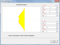
HornResp currently has a "Driver Front Volume" feature which can be used to calculate, well, the volume in front of the driver.
Would it be possible to also include the calculated CSA through the center of the driver's cone as well? That would be useful for chaps like me who are looking at ways of including "cone compensation" in our builds, like the example attached.
Attachments
@ Kolbrek
Sure they could. But having the Same units already to copy/paste from a PDF etc into HR etc, would just make it quicker 🙂 For eg, in WinISD we can click on many different T/S etc units & change to OUR preferences 😉
That's why having the units in HR the way most manufactures publish them, would help avoid possible confusion in the first place 🙂
Agree
@ Brian Steele
Looking @ your screenie for eg, it's maybe debatable where the CSA actually begins. As far as locating it for pressure etc measurements/sims goes anyway. Is it @ the very beginning, or the centre of the driver, or the end edge of the driver, or ?
Why not just let people learn such basic stuff, like converting from mm/N to m/N?
Sure they could. But having the Same units already to copy/paste from a PDF etc into HR etc, would just make it quicker 🙂 For eg, in WinISD we can click on many different T/S etc units & change to OUR preferences 😉
Selectable units could also be confusing, especially if people were to compare HR screenshots with different units.
That's why having the units in HR the way most manufactures publish them, would help avoid possible confusion in the first place 🙂
It could of course be useful to include the alternative Rms unit in the HR help file, though.
Agree
@ Brian Steele
Looking @ your screenie for eg, it's maybe debatable where the CSA actually begins. As far as locating it for pressure etc measurements/sims goes anyway. Is it @ the very beginning, or the centre of the driver, or the end edge of the driver, or ?
@ David McBean
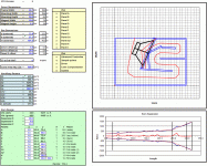
Hi, i don't know whether it's me, or a bug ? I've been tinkering with TL OD's & then tried simming with more than one driver in parallel. After i'd had a look @ a few graphs i went back & selected just one again. However, for eg the max SPL graphs still showed results for more than one !
*
As well as simming parallel/series drivers in the same box, could you add the facilty to show the effects of parallel/series boxes ? 😉
Also, System Design With Driver & System Design From Specifications The default is for a hyperbolic-exponential horn in each case, but having the options of other alignments as default too would be Very nice 🙂
Regards
Would it be possible to also include the calculated CSA through the center of the driver's cone as well?
Hi Brian,
Just to clarify, when you say the calculated CSA through the centre of the driver's cone, do you mean the cross-sectional area as highlighted in yellow in the attachment? If not, could you please provide further information.
Kind regards,
David
Attachments
Hi Zero D,
I have not been able to replicate the problem. Everything is working fine at this end. Do you have a specific record and sequence of events that leads to the error, that I could try?
After calculating results, select Tools > Multiple Speakers or press Ctrl+K from the Acoustical Power window.
Sorry, the System Design tools are limited to hyperbolic-exponential horns only.
Kind regards,
David
I've been tinkering with TL OD's & then tried simming with more than one driver in parallel. After i'd had a look @ a few graphs i went back & selected just one again. However, for eg the max SPL graphs still showed results for more than one !
I have not been able to replicate the problem. Everything is working fine at this end. Do you have a specific record and sequence of events that leads to the error, that I could try?
As well as simming parallel/series drivers in the same box, could you add the facilty to show the effects of parallel/series boxes ?
After calculating results, select Tools > Multiple Speakers or press Ctrl+K from the Acoustical Power window.
Also, System Design With Driver & System Design From Specifications The default is for a hyperbolic-exponential horn in each case, but having the options of other alignments as default too would be Very nice 🙂
Sorry, the System Design tools are limited to hyperbolic-exponential horns only.
Kind regards,
David
Just to clarify, when you say the calculated CSA through the centre of the driver's cone, do you mean the cross-sectional area as highlighted in yellow in the attachment?
Yup, that's it exactly. I think just an extra line in that provides the CSA at that point should be enough.
Yup, that's it exactly.
Hi Brian,
Thanks for the confirmation. You have made me curious - how would this information be used in practice?
I have read through your 'Damping cone excursion below resonance and equalizing pressure' and '"cone compensation" - a test case' threads, but am not exactly sure what it is that we are trying to achieve. The terms "cone correction", "cone compensation" and "restriction" have got me confused 🙂.
As far as I can gather, it seems that we perhaps want to understand the impact on performance of three different design techniques:
1. Increasing the throat chamber volume Vtc in the simulation to account for the front-side diaphragm cone volume (which can be calculated using the Driver Front Volume tool).
2. Inserting a solid "phasing" plug in front of the diaphragm cone to fill in most of front-side diaphragm cone volume, so that the throat chamber does not become overly large.
3. Inserting a constriction port between the throat chamber and the horn, with the aim of better equalising pressure across the diaphragm (for an offset driver or tapped horn, the port can be specified using Ap1 and Lp).
Is my understanding correct? If not, can you please set me straight 🙂.
Kind regards,
David
Hi David. cone correction = cone compensation = accounting for the volume of air trapped in the driver's cone. I'll have to stick to using only one of those terms in the future to avoid confusion 🙂.
I'd say you're correct on all three for the most part. On 3, the constriction can be emulated as you suggested if the TH is laid out accordingly, but I'm not sure that approach would work for how the restriction at S2 is implemented in a design like the TH115.
On the CSA thing, my thinking at the time was that providing an idea of the CSA through the center of the driver's cone would give an idea of how much the CSA @ S2 would have to be reduced to compensate, but maybe I should just look at the issue in terms of volumes rather than CSA.
On the CSA thing, my thinking at the time was that providing an idea of the CSA through the center of the driver's cone would give an idea of how much the CSA @ S2 would have to be reduced to compensate, but maybe I should just look at the issue in terms of volumes rather than CSA.
Hi Brian,
I can certainly provide the CSA information if it would be of any value to you, but if the aim of the exercise is to make the effective total both-way cross-sectional area at the offset horn entry point equal to that of the driver diaphragm, then perhaps a simpler approach would be to set S2 = Sd / 2. That should be close enough for all practical purposes.
Please let me know if you would still like the CSA information to be provided.
Kind regards,
David
Please let me know if you would still like the CSA information to be provided.
Thanks David. I don't think it will be required at this point, as it seems for bass-horn use all that's necessary is to ensure that the front-side cone volume is accounted for in the sim, which is easily done via increasing Vtc accordingly. My little test suggests that this is good for sims up to 300 Hz for a TH based on a 12" driver, way higher than such a TH would normally be used.
http://www.diyaudio.com/forums/subwoofers/276742-cone-compensation-test-case-5.html#post4381569
Now, about accounting for the volume displaced by the driver's body sitting in the mouth of a TH.... 🙂.
Last edited:
Hi Brian,
Excellent, I was hoping you would say that - it saves me some work 🙂.
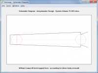
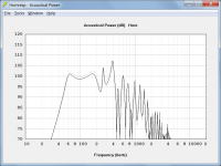
Provided that the airway is not unduly obstructed, the impact on the overall result should not be great. Out of interest, I tried halving the cross-sectional area at the mouth entry point on a standard reference design, to account for the presence of the driver body.
Attachment 1 shows the standard design.
Attachment 2 shows the modified design, with area at the mouth entry point reduced to account for the driver body.
Attachment 3 shows the response of the standard design (grey trace) compared to the response of the modified design (black trace).
The effect on the response would be more significant if the orientation of the driver was reversed - that is, if the body of the driver intruded at the throat end rather than at the mouth end of the tapped horn.
Kind regards,
David
I don't think it will be required at this point,
Excellent, I was hoping you would say that - it saves me some work 🙂.
Now, about accounting for the volume displaced by the driver's body sitting in the mouth of a TH.... 🙂.
Provided that the airway is not unduly obstructed, the impact on the overall result should not be great. Out of interest, I tried halving the cross-sectional area at the mouth entry point on a standard reference design, to account for the presence of the driver body.
Attachment 1 shows the standard design.
Attachment 2 shows the modified design, with area at the mouth entry point reduced to account for the driver body.
Attachment 3 shows the response of the standard design (grey trace) compared to the response of the modified design (black trace).
The effect on the response would be more significant if the orientation of the driver was reversed - that is, if the body of the driver intruded at the throat end rather than at the mouth end of the tapped horn.
Kind regards,
David
Attachments

- Home
- Loudspeakers
- Subwoofers
- Hornresp