I am not arguing with the bootstrap mod doctormod, I am not dismissing anything.
My post wasn't meant offending in any way. For me, there is no difference with/without snubber -> soundwise. I have it in for EMI/EMV reasons to limit Over/Undershoot/Ringing while hardswitching as i don't use an output-filter. 🙂
It is unfortunate for me tat DC power bypass caps are smd..
What i had in mind was the 1nF smd cap near the PVCC-pins, these are also "just" for EMI/EMV reasons. (Depends on the layout as well)
Last edited:
Wasn't suggesting yours was doctormod. It might be I am just not getting point across, and pig headed, it might be from other end. A lot can be read into mail only communication when haven't ever socialised with a person.
Concerning your output.... Do you use a ferrite bead set up? I am undecided on this.
Concerning your output.... Do you use a ferrite bead set up? I am undecided on this.
Yes i do.
Amp:
TPA3132D2 - minimum 50 50W class D amplifier | #360customs
My measurements are shown here:
Tpa3132d2 vs. MAX9709 Messungen EMI/EMV | #360customs
(At the bottom, i compared the impact of wired/smd ferrites to the filter)
The actual revision is attached.
Amp:
TPA3132D2 - minimum 50 50W class D amplifier | #360customs
My measurements are shown here:
Tpa3132d2 vs. MAX9709 Messungen EMI/EMV | #360customs
(At the bottom, i compared the impact of wired/smd ferrites to the filter)
The actual revision is attached.
Attachments
Aye. Those are the ones I was mentioning....
That's the "Phillips" class 1 NPO.
I had asked if the 1nf is correct place on the power connector side, opposite end to the slave resistor/cap. Or, whether the silkscrn showing the 10nf & 1nf wrong way around, as wasn't sure. Didn't get an answer.
Greetings, I started this thread yesterday and made it to post #280.
Is there a list of "go to" posts or a summary?
Thanks
Is there a list of "go to" posts or a summary?
Thanks
Greetings, I started this thread yesterday and made it to post #280.
Is there a list of "go to" posts or a summary?
Thanks
Hi Ed
Have a scan through this lot. I'm not sure if it's has been updated in while
TPA3116D2 Boards - diyAudio
My blue/black board arrived yesterday. I popped in the Oscons this morning.

These boards really do sound pretty good, regardless of cost. I just need to tame the HF a bit as I find it a touch fatiguing.
Richard
Last edited:
Greetings, I started this thread yesterday and made it to post #280.
Is there a list of "go to" posts or a summary?
Thanks
No, unfortunately the OP posted the first post and never touched the thread again. Otherwise it would have been a living first post with a TOC if I or others active here had started it.
I ordered the Blue/black board from AE and while I'm waiting for delivery, I'm trying to source components for the mods, mentioned in
TPA3116D2 Boards - diyAudio
"The oscons" are easy and cheap here in Europe, easily available from Farnell, but all the other components are costly to obtain, as they all come from the US.
Can anyone suggest "european" components for mods? And by european, of course I mean readily available, not made in. 🙂
Thanks, guys.
I had asked if the 1nf is correct place on the power connector side, opposite end to the slave resistor/cap. Or, whether the silkscrn showing the 10nf & 1nf wrong way around, as wasn't sure. Didn't get an answer.
Don't worry, there isn't anything to improve or deteriorate that far away from chippins.
Tripmaster, That link will be of great value. Thanks
I've already ordered a 2.1 board through AliExpress. It appears to be the "Breeze 2.1".
I plan to use it in a "travel rig" while working away from home.
Time to catch up.
I've already ordered a 2.1 board through AliExpress. It appears to be the "Breeze 2.1".
I plan to use it in a "travel rig" while working away from home.
Time to catch up.
Last edited:
Don't worry, there isn't anything to improve or deteriorate that far away from chippins.
I am not worrying irribeo, just would like to know.
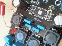
The board I photo'd and posted had silkscreen with the 10nf nearest power input and 1nf nearest input caps (on the power cable side of board), but my second board has no values on that side at all and the size of the smd's on it do not match those on other side of it.
If I can get confirmation of the order for the board I posted, then at least I'll be able to figure out the board with no silkscrn and different sizing of smd.
You won't be able to. Silkscreen when there, doesn't tell you value on the Chinese boards, without silkscreen you know as much. Measure them if you want to know. But again, pcbtrace distance makes replacing them there useless, find a better pcb or place them as close as possible to chippins.
Perhaps it is my fault, I tried to read as much pages of this thread as I could but I did not find if someone tried to configure Ybdz "Weiner" green or blue board into PBTL and if it is therefore possible.
In the positive case, if filter values (inductor ans resistance) should be changed.
I would also ask if something else should be changed in the case one would like to use it for a 4 ohm load.
Thanks everybody
In the positive case, if filter values (inductor ans resistance) should be changed.
I would also ask if something else should be changed in the case one would like to use it for a 4 ohm load.
Thanks everybody
You won't be able to. Silkscreen when there, doesn't tell you value on the Chinese boards, without silkscreen you know as much. Measure them if you want to know. But again, pcbtrace distance makes replacing them there useless, find a better pcb or place them as close as possible to chippins.
On the 2 YJ boards, bought and posted from China, all but the 3 values mentioned are on silkscrn.
I am not saying the components are values silksrn has, that's quite clear from output resistors, lc capacitor etc.
I am trying to get confirmation of the order of the 3 components on each end of the IC as layout different to data sheets, and also original danzz schematic I found here.
I don't care whether or not to change any components there, although if the 3 without values on silkscrn are totally wrong they should be corrected, I am trying to understand the layout at the end of IC compared to published circuits. If I can't tell what's going on with the circuit, might as well stop working on boards and throw in bin.
All I am doing is asking for another whom has, or even has a photo of, removed heatsink on YJ blue/black boards to be kind enough of confirming the layout of the 3 smd components at the end of the 3116 IC on the side of the board that the power cable connectors are on.
Is that so much to ask?
the silkscreen on one of yours is identical to one of mine. does that help?
Not particularly. Why your being so ridiculous about this I have no idea. As you pointed out, the silkscrn isn't the focus.
Why don't you just bleeding confirm the order? Or, say if the board with the silkscrn I have that shows the 6 component values all printed is the one that matches correct circuit.
I thought you were a helpful, and knowledgeable member of the 3116 thread from your posts over time reading through. But opinions change heir irribeo.
Oh, and as I have mentioned before, I only have a multimeter which is not a way of measuring the capacitance.
The YJblue doesn't completely match the danzz schematic. You showed through hole ceramics on one of your boards, you didn't show another, mine and yours have silkscreen 10nF, 104, 1nF chinese rightside psudecoupling, 1nF, 104 chinese leftside psudecoupling. A board you didn't show might have other pcb traces/components and as said, danzz schematic differs, that schematic has 104 and 1nF in that order both left and right.
It still doesn't help you with the board you did not show, nor does it tell you the board you showed has 100nF when silkscreen suggests 104 etc.
*chinese rightside= Rinput side board
It still doesn't help you with the board you did not show, nor does it tell you the board you showed has 100nF when silkscreen suggests 104 etc.
*chinese rightside= Rinput side board
Last edited:
The YJblue doesn't completely match the danzz schematic. You showed through hole ceramics on one of your boards, you didn't show another, mine and yours have silkscreen 10nF, 104, 1nF chinese rightside psudecoupling, 1nF, 104 chinese leftside psudecoupling. A board you didn't show might have other pcb traces/components and as said, danzz schematic differs, that schematic has 104 and 1nF in that order both left and right.
It still doesn't help you with the board you did not show, nor does it tell you the board you showed has 100nF when silkscreen suggests 104 etc.
Really irribeo!
Let's work in reverse of you reply....
Your intelligent enough to know "104" is the marking for 100nf..... i.e. 10 followed by "4" zero's i.e 100000pf = 100nf.
Two boards look to have same traces here. Which is obviously why I didn't post another example PIC, and used posted PIC example in my question.
I was asking if the posted PIC component value layout was correct, as then I would know that my "other" board was laid out that way.
My unsureness simply came from the fact that the 1nf of the "10nf/104/1nf" rightside is furthest away from IC pins compared to left side. And having no values on silkscrn of other didn't help to solve my query.
But of course, your intelligent to know that, and I expect it was a way to wind me up. Like a dog chasing its tail!
Thank you for confirming your board layout, finally.
- Home
- Amplifiers
- Class D
- TPA3116D2 Amp

