What software was that you measured with xrk? Dont think ones i have, freeware versions, have FR and HD measuring.
Has any body tried Jerry's 3116D2 board and if there are any reviews/ comparisons. Appreciate the help
DIY Electronics KAA10021 Kit
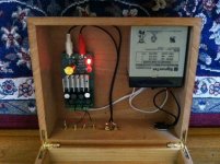
I just finished Jerry's kit for a portable/battery powered system. The shipping was lightening fast and went together in 2 hours (I have to take my time since I am color blind and had to double check everything with my wife). I was going to do the snubber mod right away since I had the parts but wanted to evaluate it in stock form first. I chose 32db for the gain since I will be often using an iPod/iPad as a source. The battery is a 12v 5a SLA.
This is a very nice sounding amp. It has the nice detail, great bass, and that slightly forward mid range sound of the TPA3116D2 that we have come to love. I don't detect any graininess in the female voice that I've heard in the stock YJ Black/Blue and Red boards (I am listening to an SACD of Diana Krall right now). It is pretty smooth in the upper registers. It is a bit more holographic too, maybe even more so than my modded Danzz board with Oscon caps, snubber mod, Bourns inductors, and Astron PS. But the latter amp is more transparent and has punchier bass. I also have the SMSL SA-36A Pro, which, even with Oscon caps, sounds much too bright for my tastes. An added bonus is that there is no turn on pop; it's dead quiet. At power down, there is a faint thud. Also, with a source connected and the volume at full, I hear no hiss! Sweet! So right now I would rank this amp just behind my modded Danzz board. For $50 (with parts and humidor included) this amp has exceeded my expectations.
Attachments

What software was that you measured with xrk? Dont think ones i have, freeware versions, have FR and HD measuring.
What software was that you measured with xrk? Dont think ones i have, freeware versions, have FR and HD measuring.
What "snubber"? The "zobel" as in zobel versus non-zobel of the TPA??
The snubbers TI 3116evm has mounted pre-inductor, like STM's differential snubber pre-inductor.
Both have no direct influence on audioband frequencies, both are very similar, even if you change values with creative calculations 🙂 (and try to simulate)
No direct influence on audioband frequencies? undeniable influence on harmonics, voltage and phase behaiour within said "audioband".
No direct influence on audioband frequencies? QUOTE]
That is correct.
What software was that you measured with xrk? Dont think ones i have, freeware versions, have FR and HD measuring.
I use REW - it measures Freq Response, Phase (minimum, excess, absolute), Harmonic Distortion (up to 10th harmonic), Impulse Response, Step Response, Waterfall, Cumulative Spectral Decay, etc.
REW - Room EQ Wizard Room Acoustics Software
Greatest free (or even if it were not free) measurement program ever. 🙂
The snubbers TI 3116evm has mounted pre-inductor, like STM's differential snubber pre-inductor.
Both have no direct influence on audioband frequencies, both are very similar, even if you change values with creative calculations 🙂 (and try to simulate)
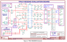
TI's EVM circuit has pre-LC snubbers (aka the "bootstrap snubber" because it is connected to the bootstrap cap), and post LC snubbers. It is very well filtered and perhaps is why it sounds is very clean. Unfortunately, 98% of the Chinese TPA3116 amps went for the recommend circuit in the non-EVM board (which, btw, has an error for the master/slave RC value that renders the slave amp un-sync'd and free-running).
Here is the non-EVM circuit that most amp manufacturer's use:
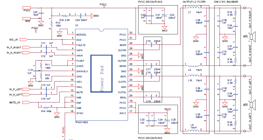
Here is the EVM circuit for those who may have forgotten. The question to ask is, if we add a 0.1uF and 10R Zobel across the inputs to the two legs of the L's on each side, will that help or hurt this circuit. Seems awfully complex now.

Some manufacturer's (like SMAKN) leave off the output snubber resistor and cap altogether to save on cost and PCB real estate.
Attachments

Last edited:
Well there are TI papers out there regarding filterless class D outputs. Even the 3116 datasheets mention very briefly it can be ommited.
no easy answer.
i am grateful for your testing. there clearly is a difference in graphs, which collate with spice circuit tests I did.
and, more relevant, is that at leat 3 of us hear the differences.
as with the power decoupling caps, the difference is a personal preferance.
no easy answer.
i am grateful for your testing. there clearly is a difference in graphs, which collate with spice circuit tests I did.
and, more relevant, is that at leat 3 of us hear the differences.
as with the power decoupling caps, the difference is a personal preferance.
Has anyone already, or could they, post a pic of the leg 17 resistor to leg 18 mod done. I know what hass to be done, just seeing it helps to figure out it my skill with iron and sucker will be up to it! lol.
Both have no direct influence on audioband frequencies, both are very similar, even if you change values with creative calculations 🙂 (and try to simulate)
Irribeo, if the "creative calculations" is directed at me for the Boucherot cell values, I apologise. I thought following the namesake of the circuit, John Guy, Rod Elliot, and others was the wrong thing to do.
lets all follow the EVM board bootstrap mod values, and continue to use the output zobel resistors fitted at factory which dont match the "EVM datasheet", or the "3116 with AM avoidance datasheet" values anyway!!!
ho hum.
Irribeo, if the "creative calculations" is directed at me for the Boucherot cell values, I apologise. I thought following the namesake of the circuit, John Guy, Rod Elliot, and others was the wrong thing to do
It is "creative" to use 10 ohm as resistance for the 10uH inductor in your calculations.
lets all follow the EVM board bootstrap mod values, and continue to use the output zobel resistors fitted at factory which dont match the "EVM datasheet", or the "3116 with AM avoidance datasheet" values anyway!!!
ho hum.
TI 3116 EVM board has 10 ohm & 330pF snubber on each output befor inductors. It is only a mod if your ampboard isn't a TI3116 EVM. Datasheet mentions pre-inductor snubbers could be 18 ohm & 330pF.
After inductors the TI 3116 EVM and the datasheet have a 10nF & 3.3 ohm snubber on each output, haven't seen any other value in TI 3116 documents. And they do not call it a Zobel, do they?
It is "creative" to use 10 ohm as resistance for the 10uH inductor in your calculations.
TI 3116 EVM board has 10 ohm & 330pF snubber on each output befor inductors. It is only a mod if your ampboard isn't a TI3116 EVM. Datasheet mentions pre-inductor snubbers could be 18 ohm & 330pF.
I'll have to just take your word for it then as you haven't included a notation of how you know this.
As I pointed out, the guides of linkwitz, and Ti engineers documents on Boucherot cells use equations of R=coil resistance. As that was not known of xrk inductors I inserted a value. I obviously inserted the same as data sheet. I did explain myself.
[/QUOTE=irribeo;4359453]
After inductors the TI 3116 EVM and the datasheet have a 10nF & 3.3 ohm snubber on each output, haven't seen any other value in TI 3116 documents. And they do not call it a Zobel, do they?[/QUOTE]
Has anyone bothered to check the resistance across the output "snubber" resistor when they get it through post? The YJ blue/blacks I received are all 5+ ohms. Not 3.3 as data sheet. So they do not match data sheets, as noted.
You are right of course, in the data sheet the "bootstrap snubber mod" layout is not called a zobel, nor is the resistor/cap in output filter. But the correct electrical circuit name for that configuration going to GND is "Zobel", as the mod I have suggested is called a " Boucherot cell". In each configuration, their purpose, and behaviour is different, but what the "snubber mod" and "output resistor/cap" are is Zobel circuits. I just checked, and the place the datasheets only mention of the "snubber" by that name, including your suggestion of 18ohm is while talking about ferrite bead output filters, not LC. So should we all blindly rip out the LC and put in ferrite!!! I think not.
I do find this a bizarre subject to quabble over, if following the evm and 3116 with am avoidance data sheets to the letter is required, don't go swapping out DC cap values, inductor values, input cap values etc etc.
If trying to improve the 3116, and other boards to extract the best electrical performance, and sound then we must assess all electrical circuit possibilities. And assess whether technical knowledge gathered by a range of sources, including many other Ti published documents on class D, are applicable. For example, I am currently reading a chapter on switching regulators by Walt Kester and Brian Erisman. A class D IC basically is a switching regulator, and these 72 pages cover a vast range of modulation, output types, etc etc.
Xrk graphs showed differences, spice shows differences, I am not the only one to hear the differences. As with the differences in sound it produces, whether anyone tries this mod or not is personal choice. Exactly the same as some using 330uf, others using 470uf DC caps, or differences between input caps.
I don't see the wiki being edited down to only 1 value for each mod because a particular person says it is right, and that is wrong. Just as I have never said the "bootstrap snubber" is wrong, as I understand the difference's in its purpose, and paid attention to the reported results of those whom carried it out.
That's all.
YJ uses whatever components, capacitors and resistors available to them, close to datasheet. The resistors have had different values just like the capacitors in the output.
Every time you say your spice simulations show a difference in audioband for the snubbers you tried, I will say spice simulations will show no difference. The difference here is circuit you used for simulation and adding 10 ohm dcresistance for 10uH inductor for example?
Every Zobel or Boucherotte cell is a snubber, not every snubber is a Zobel or Boucherotte cell. TI and STM use the name snubber, STM enigeers clarify use of the snubber in class D !!! outputfilter
"Snubbers
When the output of a Class-D amplifier switches there normally is a "dead" time between the time when one transistor is turned off and the other transistor is turned on. The dead time is necessary to insure that both transistors are never conducting at the same time, which would cause large currents to flow from the power supply to ground through the transistors. However, the dead time causes a problem because it interrupts the current flowing through the inductors. Snubbers are normally used on the amplifier outputs to provide another path for the inductor current during the dead time.
There are two types of snubbers. Amplifiers with BTL outputs can use a differential snubber, with a single resistor and capacitor in series in between the two outputs. Common-mode snubbers have a resistor and capacitor in series from the output to ground and can be used with either single-ended or BTL outputs.
Common-mode snubbers for amplifiers with BTL outputs use twice as many parts as a differential snubber but they may reduce harmonic distortion. The type of snubber to use will depend on the application. The amplifier manufacturer will normally recommend values for the snubber components." EEtimes "Understanding output filters for Class-D amplifiers"
So both the TI and STM enigineers select snubber as a name, probably because they don't want to confuse us.
Can you add a speaker Zobel, yes, I do, with any of these prefilter feedback class D designs when they have an LC filter.
YJ uses whatever components, capacitors and resistors available to them, close to datasheet. The resistors have had different values just like the capacitors in the output.
Every time you say your spice simulations show a difference in audioband for the snubbers you tried, I will say spice simulations will show no difference. The difference here is circuit you used for simulation and adding 10 ohm dcresistance for 10uH inductor for example?
Every Zobel or Boucherotte cell is a snubber, not every snubber is a Zobel or Boucherotte cell. TI and STM use the name snubber, STM enigeers clarify use of the snubber in class D !!! outputfilter
"Snubbers
When the output of a Class-D amplifier switches there normally is a "dead" time between the time when one transistor is turned off and the other transistor is turned on. The dead time is necessary to insure that both transistors are never conducting at the same time, which would cause large currents to flow from the power supply to ground through the transistors. However, the dead time causes a problem because it interrupts the current flowing through the inductors. Snubbers are normally used on the amplifier outputs to provide another path for the inductor current during the dead time.
There are two types of snubbers. Amplifiers with BTL outputs can use a differential snubber, with a single resistor and capacitor in series in between the two outputs. Common-mode snubbers have a resistor and capacitor in series from the output to ground and can be used with either single-ended or BTL outputs.
Common-mode snubbers for amplifiers with BTL outputs use twice as many parts as a differential snubber but they may reduce harmonic distortion. The type of snubber to use will depend on the application. The amplifier manufacturer will normally recommend values for the snubber components." EEtimes "Understanding output filters for Class-D amplifiers"
So both the TI and STM enigineers select snubber as a name, probably because they don't want to confuse us.
Can you add a speaker Zobel, yes, I do, with any of these prefilter feedback class D designs when they have an LC filter.
Irrebeo,
Thanks for the quote from application note on snubbers. The name differential vs common mode snubbers makes sense to me. It also means that adding both differential and common mode snubbers simultaneously can be helpful - just uses a lot of parts. My concern is that 0.1uF and 10R on the upstream side of the LC filter seems like too large a cap value relative to both STM and TI designs where only a 330pF (0.3nF) is used. What happens if the cap value is too big?
Under 4Mohms for 400kHz switching frequency the ESR of capacitor is more important than value , to deal with L ripple currents.
But what do the professions in the business for over 30yrs that suggest that know!!!
Every time you say your spice simulations show a difference in audioband for the snubbers you tried, I will say spice simulations will show no difference. The difference here is circuit you used for simulation and adding 10 ohm dc resistance for 10uH inductor for example?
Just to point out the spice output circuit I used was laid out exactly as drawn in both the EVM and 3116 with AM avoidance data sheets. So are the data sheets correct or not!
And to clarify, that I did not change any values except to add xrk LC values, giving the L a resistance of 10ohms. At the time of giving said resistance to L I did not know the equations would give the same result values as 7492 data sheet. (Equations not from that datasheet or author). It just happened to turn out that way.
If I used my L measured resistances of 0.05 taken last night, and used in equations, of course the values would be lower. So 7492 data sheet using wrong R for L, unless the calculation and resistance used are noted.
And still unaware why bootstrap snubber in 3116 EVM is those values, as data sheet doesn't note why, and everyone seems to follow them.
These are the problems with most product data sheet values. They do not include how they have been determined, so "cross modding", or even optimising is useless unless we gather other sources on the subject for calculations.
If I have suggested something, I reveal the source of calculation. As I did.
I never said anything about sound stage, did I?
The measurements, as mentioned, were made with the speaker and mic untouched (position not moved or touched at all) - only amp was disconnected to perform the Zobel mod with a soldering iron or to swap amps to 7492. Yes, calibrated Dayton UMM-6 mic was used along with REW software.
This was adressed to stanleyburbick, not you. 🙂
------------
Beside this, those 330p+10R snubbers are evaluated for the EVM board. So having a different board may require different values as the physical board parameters, layout, track routing/width also accounts into this. (stray capacitance/inductance/impedance, inductor parameters, dimensions..)
I.e. i run 220p+10R in my filterless implementation.

Everyone here is doing a 330p/10R mod and confirms that there is a "huge" improvement, but noone did a reliable measurement showing this "improvement".
Even changing an SMD 1nF cap for a wired "Philips" one "improves".. Sure? Leads add (alot) of additional inductance and may form an additional resonant-tank.
Just saying..

And still unaware why bootstrap snubber in 3116 EVM is those values, as data sheet doesn't note why, and everyone seems to follow them.
These are the problems with most product data sheet values. They do not include how they have been determined, so "cross modding", or even optimising is useless unless we gather other sources on the subject for calculations.
If I have suggested something, I reveal the source of calculation. As I did.
True story. I would guess that those 330p+10R were determined empirically for this specific board-layout. So doing a different layout will normally result in different values. This 330p+10R snubber is in there to limit the over/undershoot while switching "hard". The time-constant needed can be determined with an osciloscope. But this over/untershoot, or ringing, depends on the layout and used parts.
Regards,
doc
Last edited:
I am not arguing with the bootstrap mod doctormod, I am not dismissing anything.
The reasons I haven't yet done it are that I don't have final LC values, I also haven't calculated values of my proposed "snubber" because not final LC values....which will have a larger effect on my proposal final values.
I have only just started looking at finalising final LC values, to lead to snubber values, as I needed to finalise my input decoupling values first, and then from those my pllxo. Now I have got those sorted, my hunt is on for the right components for purpose.
It is unfortunate for me tat DC power bypass caps are smd, as I prefer largest physical size for value here, not true for the main DC power cap tho.
I am obviously rubbing people up the wrong way on here, for whatever reason. So, I'm just gonna keep to asking questions if I don't quite understand something said, or there mod, or about the 3116.
I have more than 1 board, as I am building two identical for my system, and son wanted a military ammo box portable system.....he plays Xbox Modern Warfare etc a lot.
I am modding just 1, a step at a time for the comparison. Maybe eventually, when a board is complete, I 'all post comparison sound files, and speaker measurement images of the completed amp against unmodified data sheet value board.
But for now, I am pleased with progress in how the modding of my amp is improving its performance, and the sound coming through the single source 8inch vintage paper cone full range woofer.
- Home
- Amplifiers
- Class D
- TPA3116D2 Amp