J knocked up 2 more spice graphs below. I didnt change any values, or the order of lines on graph already mentioned.
The difference between these graphs is..
Boucherot cell test 5 with ONLY bootstrap mod on Both channels.
Boucherot cell test 6 with ONLY Boucherot cell mod on BOTH channels.


NOTICE THE RIGHT GRAPH.... Boucherot cell only on both channels..... Voltage and phase of both channels virtually perfectly inline with each other!!!!! SWEET.
The difference between these graphs is..
Boucherot cell test 5 with ONLY bootstrap mod on Both channels.
Boucherot cell test 6 with ONLY Boucherot cell mod on BOTH channels.
NOTICE THE RIGHT GRAPH.... Boucherot cell only on both channels..... Voltage and phase of both channels virtually perfectly inline with each other!!!!! SWEET.
Last edited:
Thanks for running the sims. I have a hard time understanding what the graphs are showing. There is no legend and the circuit diagrams are too small to see the component values. It's ok I trust you but I guess I don't know what the ideal graph is supposed to look like. I have 10R and 100nF lying around as SMT parts. I guess I can solder that on and see.
Thanks for running the sims. I have a hard time understanding what the graphs are showing. There is no legend and the circuit diagrams are too small to see the component values. It's ok I trust you but I guess I don't know what the ideal graph is supposed to look like. I have 10R and 100nF lying around as SMT parts. I guess I can solder that on and see.
Y3s, sorry about that. Used scrn print and paint and it saved as jpg. I could redo if graphs not clear enough as I saved all files this time.
I described the legend of V👎 lines and colours in post. And each PIC has description of which mod or combination used in the graph box header line on left side.
Basically, the output circuit values are as 3116 data sheet. I used you LC of 10uH/680nf and the corresponding 4ohm "driver" resistor.
The bootstrap mod values 10R/330pf as per evm data sheet.
The boucherot cell 10R/100nf as calculated for the LC values.
Need to do one with both mods on both channels together to show comparisons, so may improve all and post again to help.
Here's my interpretation of the graphs....
Starting with the first 4, left to right:
Boucherot cell test 1.
This graph does not have either bootstrap, or boucherot cell mod on the top channel.
It does have the evm data sheet bootstrap mod on the lower channel.
As you can see, both channels voltage and phase line pretty much line up with each other. Whether or not the angle/values in dB & degrees is good or not I don't actually know. But they do line up.
Boucherot cell test 2.
This graph also does not have bootstrap or boucherot cell mod on top channel.
On the bottom channel this circuit has the boucherot cell mod.
As you can see, the voltage and phase lines pretty much replicate the graph 1 result. So, on first looking, you could assess that both mods are the same. But look closer to voltage and phase lines above 10kHz.
You will see that the channel with boucherot cell has both voltage and phase lines which ever so slightly fall below those of the top channel.
The interesting thing to myself here is that the boucherot cell has moved the voltage line enough as to align them exactly 38degrees apart (not entirely clearly shown) and has also move them closer together by around 2 degrees at 20kHz. But the 38 degrees is another issues I have not found enough info on to elaborate much.
Boucherot test 3.
This graph shows the circuit with Evm bootstrap mod on top channel, and the boucherot cell mod on the bottom channel. It is this graph where differences appear.
As you can see, the effect that having a mod in both channels changes the bootstrap mod voltage lines dramatically.
The voltage lines of the top channel (yellow and blue) start low on left about 10 degrees apart, rising to level of at around 3500Hz. There phase lines also split apart after the voltage starts to level. And the voltage ends 10 degrees apart.
Whereas, the boucherot cell mod, bottom channel voltage line (red and pink) are identically horizontal up to 1kHz then slowly roll apart to end about 10 degrees apart, with very little difference in the behaviour of their phase lines 100degrees lower.
What causes this? I would presume having another mod in the other channel causes the bootstrap mod to behave so differently, but is it any mod. Or just placing the boucherot cell in other channel that causes bootstrap voltage and phase to do this!
Boucherot cell test 4.
This graph has only the bootstrap mod in the top channel, and in the bottom channel I added both the bootstrap mod and boucherot cell.
Again, the bootstrap mod on its own is affected in same way as graph 3.
Yet, adding the extra boucherot cell to the bootstrap mod in the bottom channel (red & pink) hasn't looked to alter the results as compared to graph 3.
So adding the boucherot cell to a channel with bootstrap mod already fitted doesn't look like it will make a difference to that channel, but will continue to dramatically change the other channels voltage and phase which only has the bootstrap mod.
This makes me think that anyone testing the boucherot cell mod with the bootstrap mod already fitted would see a significant difference if they were to do test how I did. i.e. to only mod the 1 channel with boucherot cell & bootstrap, leaving the other channel with just bootstrap mod, and run side by side outputting to identical speaker drivers.
So now moving to the 2nd post with graphs 5 & 6, starting with the left graph.
Boucherot cell test 5
This graph shows voltage and phase for both channels having the bootstrap mod. No boucherot cell is used in this circuit. This I did to test whether it was just the boucherot cell making the differences to the results of graph 3.
As you can see, it wasnt the boucherot cell in opposite channel to bootstrap mod causing graph 3 results. A bootstrap mod in both channels causes those results to the voltage and phase.
The conclusion of this, is that any resistance in opposite channel causes the bootstrap to behave this way. Proving the bootstrap and boucherot cell mod are NOT the same mod, and that the bootstrap mods role is not to deal with resistance between 3116 and LC.
To test this, lets look at the last graph above.
Boucherot cell test 6.
This final graph in 2nd post of graphs above shows the circuit with only the boucherot cell fitted on either channel. Their is no bootstrap mod in this circuit. The exact opposite of graph 5.
What d9 we see?
The graph pretty much resembles the first 2 graphs. Both graph 1 with bootstrap mod on only 1 channel, and also graph 2 with only the boucherot cell on one channel. But this is a boucherot cell on both channels. Its not behaving as graph 5 did with the bootstrap mod on both channels.
Confirmation that the boucherot cell behaves differently to the bootstrap mod. Confirmation that unlike the bootstrap mod not behaving with another mod on opposite channel, the boucherot cell behaves itself regarding voltage and phase lines entirely.
This is because the boucherot cell has the sole purpose of dealing with resistance, and stabalizing it. A different mod.
My explanation of why I heard differences in the channel with boucherot cell alongside a channel without boucherot cell or bootstrap mod.....,.
Graph 2 compared to graph 3. And also, I believe the very slight shifting of the phase to a more uniform alignment, and the 38 degrees I mentioned above. I am learning I need more evidence to discuss things on here, so until I find some more info on that I am gonna keep quiet on that one.
All I will need to do later today, is to take the circuit from this graph and run boucherot test 7, which will show the bootstrap mod AND boucherot cell on BOTH channels as a comparison to graph 1, 3 & 4.
I hope this makes the graphs a little clearer. Its awkward knowing what your evidence shows but not being able to convey it so others understand.
Hi guys- I finally got a Sure 3116 up and running. It has a really loud turn on pop on one channel. It's much louder than any of the other boards I have. Any suggestions please.
You could place a 100nF smd within 2.5mm maximum distance from chippins and a bigger value smd within 6mm maximum distance from chippins to improve decoupling (reduce ripple) as TI suggests for similar amlifier. Yjblue also has a problematic bootstrap distance/inductance, so all PSU decoupling YJblue is problematic. For red and green YJ/AC boards bootstrap isn't problematic imo, other PSU decoupling sometimes even worse than YJblue. Most later 3116 ampboards have better decoupling than the three oldest boards.
(TH parts to replace SMD parts for decoupling in their original pcb location only increases inductance/distance)
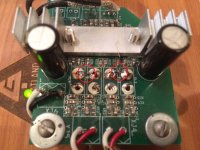
I tried to keep them close to the chip's pins by scraped the solder resist off the board to create new solder points. Someone on another forum had suggested it. Here's a pic
Attachments

Last edited:
just getting to play round with the graphs again. just thought I'd post the full circuit diagram first as xrk said the original posts werent clear.
this is all the values which are used in any of my Boucherot test circuits in spice.
View attachment 488319
this is all the values which are used in any of my Boucherot test circuits in spice.
View attachment 488319
I said I'd put a complete circuit of bootstrap mod and boucherot cell spice example.
heres a pic of 3 graphs for comparison. the circuit values are as above.
the only exceptions are as on each graph header.
the top is circuit without eith bootstrap or boucherot cell.
the middle graph is just with bootstrap mod applied.
the bottom graph is full circuit as about with both bootstrap mod and boucherot cell.
note, that the bottom full circuit graph resembles top original board circuit graph, BUT there are very subtle differences which begin where the two "solid voltage lines" start to seperate. This continues, which makes it "feel as though they are slightly different looking at them" despite not being able to pin point it. it looks like the difference in seperation of the voltage/phase lines makes the curves steeper/shallower!
Zobel Mod: Measurement and Sound Clips
Ok, so I finally had time to don the magifying goggles, precision tweezers, and braced myself for some fine surgery work with installing the SMT 10R and 100nF cap Zobel mod onto my v0 DUG TPA3116D2 amp. This is my original and basic test amp that has the stock non-EVM circuit (no bootstrap snubber). I thought this was a good test as I really know how this amp performs - generally a fantastic sounding amp (no OSCON's just Panansonic 560uF 35V FM's, 1uF 250V EPCOS metalized polyfilm input caps). Also it has exposed pads on top as the inductors are mounted on the bottom side. Test was conducted with 10F/RS225 FAST Ref Monitor speaker and mic on stand both untouched between no-Zobel and with-Zobel (I took amp away and added Zobel and returned and re-connected). XO is provided by miniDSP, for details of this speaker and the XO setup, refer to this thread: http://www.diyaudio.com/forums/full-range/273524-10f-8424-rs225-8-fast-ref-monitor.html
Here is a photo of the mod (inside red circles):

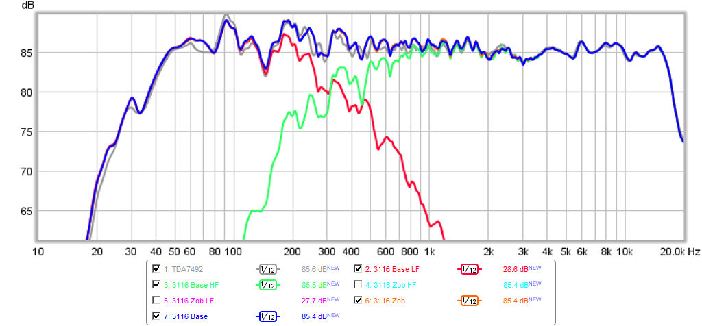
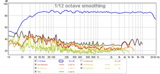
Here is the measured frequency response (FR) at 1/12oct smoothing with and without Zobel, grey line is TDA7492 for comparison, the scale is too coarse and they all land on top of one another - so the difference is very small indeed:

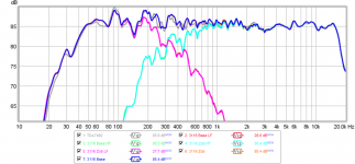
Here is the FR with just the Zobel mod and base case but no separate LF and HF cases for the base case to see if you can see any difference, and note that the blue and orange lines are pretty much on top of each other still:
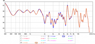
In order to compare the two, here is the expanded 1dB/div scale with 4ms gate applied and 1/48th oct smoothing - you can barely see the difference here (maybe 0.5dB difference in the 2kHz to 8kHz range with smoother response), and the Zobel (orange) mod appears to have a smoother response with less sharp of ripples in the mid range than the base no-Zobel case (blue):

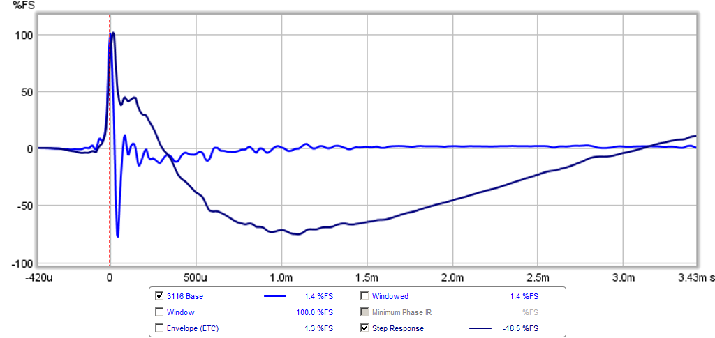
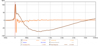
Here is the measured Impulse Response (IR) and Step Response (SR) for the base case with no Zobel:
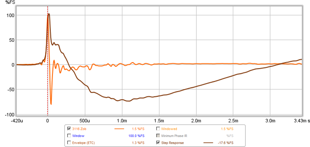
Here is the IR and SR for the Zobel mod - there appears to be a smoother rise on the SR, with less pre-ring dip:
Here is the measured harmonic distortion (HD) for the base case with no Zobel mod - below 150Hz, there is some background HVAC noise:

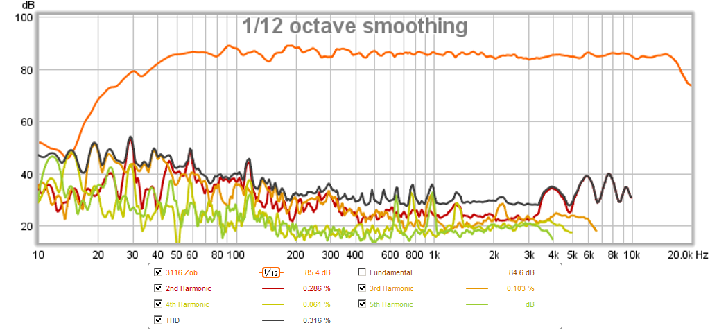
Here is the measured HD for the Zobel mod. I think there is a slight improvement in the reduction of 4th and 5th order HD from 500Hz to 5kHz (?) small in any event so not sure if real:
This is all fine and good, but how does it sound? Well, I will let you be the judge, sound clips to follow. Mic and stereo soundclips of the mono right speaker were taken at same position (0.5m) to minimize floor bounce and room reflections.
Ok, so I finally had time to don the magifying goggles, precision tweezers, and braced myself for some fine surgery work with installing the SMT 10R and 100nF cap Zobel mod onto my v0 DUG TPA3116D2 amp. This is my original and basic test amp that has the stock non-EVM circuit (no bootstrap snubber). I thought this was a good test as I really know how this amp performs - generally a fantastic sounding amp (no OSCON's just Panansonic 560uF 35V FM's, 1uF 250V EPCOS metalized polyfilm input caps). Also it has exposed pads on top as the inductors are mounted on the bottom side. Test was conducted with 10F/RS225 FAST Ref Monitor speaker and mic on stand both untouched between no-Zobel and with-Zobel (I took amp away and added Zobel and returned and re-connected). XO is provided by miniDSP, for details of this speaker and the XO setup, refer to this thread: http://www.diyaudio.com/forums/full-range/273524-10f-8424-rs225-8-fast-ref-monitor.html
Here is a photo of the mod (inside red circles):
Here is the measured frequency response (FR) at 1/12oct smoothing with and without Zobel, grey line is TDA7492 for comparison, the scale is too coarse and they all land on top of one another - so the difference is very small indeed:
Here is the FR with just the Zobel mod and base case but no separate LF and HF cases for the base case to see if you can see any difference, and note that the blue and orange lines are pretty much on top of each other still:
In order to compare the two, here is the expanded 1dB/div scale with 4ms gate applied and 1/48th oct smoothing - you can barely see the difference here (maybe 0.5dB difference in the 2kHz to 8kHz range with smoother response), and the Zobel (orange) mod appears to have a smoother response with less sharp of ripples in the mid range than the base no-Zobel case (blue):
Here is the measured Impulse Response (IR) and Step Response (SR) for the base case with no Zobel:
Here is the IR and SR for the Zobel mod - there appears to be a smoother rise on the SR, with less pre-ring dip:
Here is the measured harmonic distortion (HD) for the base case with no Zobel mod - below 150Hz, there is some background HVAC noise:
Here is the measured HD for the Zobel mod. I think there is a slight improvement in the reduction of 4th and 5th order HD from 500Hz to 5kHz (?) small in any event so not sure if real:
This is all fine and good, but how does it sound? Well, I will let you be the judge, sound clips to follow. Mic and stereo soundclips of the mono right speaker were taken at same position (0.5m) to minimize floor bounce and room reflections.
Attachments
-
 zobel-3116-hd.png164.7 KB · Views: 582
 -
 no-zobel-3116-hd.png161.2 KB · Views: 583
 -
 zobel-3116-ir-gate-4ms.png63.3 KB · Views: 591
 -
 no-zobel-3116-ir-gate-4ms.png61.2 KB · Views: 585
 -
 zobel-3116-fr-gate-4ms.png94.3 KB · Views: 583
 -
 zobel-3116-fr-all.png99.4 KB · Views: 598
 -
 no-zobel-3116-fr-all.png99.3 KB · Views: 1,914
 -
 TPA3116-Zobel-Test-Photo.jpg347.9 KB · Views: 1,364
Last edited:
Sound Clips of the Zobel Mod & Compare with TDA7492
Here are the sound clips for the above cases: TPA3116 base no Zobel, TPA3116 with Zobel, and TDA7492 amp for a comparison. There are 3 sound clips so you get a chance to check out mid range vocal clarity (A), overall balance and texture/timbre (B), and a clip that emphasizes high notes and percussion with lots of detail (C). These were, as usual, recorded using a Zoom H4 in 96kHz/24bit .wav format. I then used Audacity to trim, and amplify for peak values to be -1dB (of full scale), then encode in 320kbit/48kHz mp3 format so that it is within a size that can be uploaded onto diyAudio servers. The filename extensions are changed to .asc to allow the maximum 1.82MB filesize to be utilized. You need to change extension from .asc to .mp3 in order to listen. For A/B compariosn, best to put sound clips in a playlist and step back and forth. Audacity is great for A/B too by clicking mute/unmute on two tracks played simultaneously.
I don't want to influence your opinions so I will save my subjective comments for later after folks have had a chance to listen.
Have fun... please let me know what you think
Attachments
-
3116-No-Zobel-clip-A.asc1.7 MB · Views: 168
-
3116-No-Zobel-clip-B.asc1.7 MB · Views: 113
-
3116-No-Zobel-clip-C.asc1.7 MB · Views: 104
-
3116-With-Zobel-clip-A.asc1.7 MB · Views: 132
-
3116-With-Zobel-clip-B.asc1.7 MB · Views: 89
-
3116-With-Zobel-clip-C.asc1.7 MB · Views: 107
-
7492-clip-A.asc1.7 MB · Views: 93
-
7492-clip-B.asc1.7 MB · Views: 141
-
7492-clip-C.asc1.7 MB · Views: 76
Last edited:
Good to see some difference...not my imagination, entirely anyway.
One question with bottom two graphs the HD measurements......
What does the fact that all the Harmonic lines are much more tighter together in the zobel mod graph, compared to the basic graph?
One question with bottom two graphs the HD measurements......
What does the fact that all the Harmonic lines are much more tighter together in the zobel mod graph, compared to the basic graph?
Good to see some difference...not my imagination, entirely anyway.
One question with bottom two graphs the HD measurements......
What does the fact that all the Harmonic lines are much more tighter together in the zobel mod graph, compared to the basic graph?
Probably a reduced level of HD, if tighter together and further down from the fundamental. If tighter together but higher up then an increase.
There is a very small, more like 0.3dB difference that I can measure at the speakers - however, there may be time or transient response effects that are more audible than the measurement. It will really depend on how you think it sounds when you listen.
I don't want to influence your opinions so I will save my subjective comments for later after folks have had a chance to listen.
Have fun... please let me know what you think
Just listened, albeit through Sony headphones and a tablet device.
Clip A - to me, the clip with zobel fitted sounded like it was a much larger venue than the clip without zobel.
Clip B - her voice sounded to have much more feeling to it with zobel fitted.
Clip C - the zobel clip sounded more like a live performance, and made the clip without zobel sound like a recorded performance.
That's my basic assessment on very basic listening devices.
Well,
if you feel differences between the two, please tell where, and let XRK measure to be sure there is difference.
From my side, I am not sure there are audible differences. OK actually, I listened the clips from my PC, and it may be noisely. but as I can ear TPA3116 signature from my PC (and I can do it), I think I can ear audible differences.
For me there are no major differences. But I can be wrong.
as I can ear TPA3116 signature from my PC
issues on the voices on high frequencies. Same issue with Zobel or not.
Same issue with YJ blue board.
Maybe it comes from the file format, I know MP3 can bring noise in high frequencies as it is NOT a lossless data compression format.
For me, it does not affect the price/quality ratio of this chip => TPA 3116 is an excellent choice.
Last edited:
Well,
if you feel differences between the two, please tell where, and let XRK measure to be sure there is difference.
From my side, I am not sure there are audible differences. OK actually, I listened the clips from my PC, and it may be noisely. but as I can ear TPA3116 signature from my PC (and I can do it), I think I can ear audible differences.
For me there are no major differences. But I can be wrong.
I can't put my finger on it to explain well, as previous descriptions of my test testifies.
Clip A sounds more open and larger overall to me. I am not listening to pick out particular freq ranges or effects, its more listening to the whole sound.
Clip B is the same overall listening to sound. I do hear the highs slightly more "striking" and her voice seems to have a nicer "soft/deep" tone to it when she sings "husky".
Clip C I have no idea why the sound to me sounds more " live performance" than sitting in front of a recording. I think its just a combination of sounding more open.
You are right of course irrebeo. A blind test would have been revealing, especially as I know what I think I heard in my test of the mod. Maybe xrk could rename the sound files without revealing the mod included or not - obviously in a different order. It might eradicate bias from both sides.
I could prepare new clips from different section of song so you can't figure it out by comparing files.
I could prepare new clips from different section of song so you can't figure it out by comparing files.
Didn't think of that. Good idea.
At least your graphs showed the difference. Even if others think I am hearing things they aren't, and the mod doesn't belong there! Just think what it will do across terminals in your speaker crossovers!
issues on the voices on high frequencies. Same issue with Zobel or not.
Same issue with YJ blue board.
Maybe it comes from the file format, I know MP3 can bring noise in high frequencies as it is NOT a lossless data compression format.
For me, it does not affect the price/quality ratio of this chip => TPA 3116 is an excellent choice.
To be fair I thought xrk previous sounds files through his speakers had too much sibilance of the high female voices....for my liking anyway. But maybe that's the original recording and the speakers are genuine reproduction of that aspect.
I did notice however that my listening system for these tests showed less "hissing" in the quieter moments during the mod recordings. Probs my tablet/headphone, but definitely difference between two was noticed.
Last edited:
- Home
- Amplifiers
- Class D
- TPA3116D2 Amp