http://p10hifi.net/TLS/downloads/Bailey_TLs_2.pdf
I will repeat … Bailey's line is a resonant enclosure. It uses a quarter-wave resonance to augment bass. To be non-resonant it would need to be stuffed until it is aperiodic and the rear wave is completely absorbed.
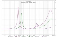
See the impedance with KEF B139 (SP1044 C1579) on the triangular cross section Bailey’s TL filed with long fiber wool
George
Attachments

See the impedance with KEF B139 (SP1044 C1579) on the triangular cross section Bailey’s TL filed with long fiber wool
George
Hi, George, thank you for the post. After so many days, I almost thought that I was the only person on this forum who ever built and measure a Bailey TL enclosure and stuffed it with long fiber wool.
I built the same triangular design as you did when I was a graduate student a long time ago. I could not afford the KEF B139 and used a Philips AD10100 instead. My measurements are shown below, impedance and response. On the impedance plot, the circles and up-triangle are free air and the hexgon and down-triangle are inside enclosure. (Sorry about the chartsmanship. It was long before the PC computer time.) Also like your results, the woofer resonance peak is much reduced from 67 ohms to 25 ohms (compared to free air) and moved up in frequency, from 32 Hz to 46 Hz.


Both of our measurement definitely show no second resonance peak of that of a vented enclosure such as the MLTL. The long fiber wool works exactly as Arthur Bailey and Leslie Bradbury described. The bass is fast (no ringing) and extend far lower than a closed box. It sounded wonderful to me. There actually a lot of similar result that appeared in the old Speaker Builder magazine in the 80's by Gary A.Galo, Roger Sanders and Robert Spear, among others.
The AD10100 does not go as low as the B139, but still got -6 dB down at about 30 Hz. The drivers had deterioted over time, the rubber surround lost resilance. The cabinet and wool still good. I got a pair of the Peerless 850146 (CSX 257 H 10" woofer) to rebuild it. The woofer should be a drop-in replacement. Very easy, right? No, my wife will not allow it back to the listening area until I replace the wood veneer. With 2 bookshelf projects ongoing, the re-veneering may take a while. 😱 That WAF!
(I used a pair of Wharfedale aperiodic with twin 7" woofers as substitute for now.)
If we can convince Dave (planet10) to measure the impedance curves of his TLS80II and Fried H. It would be very interesting.
Last edited:
If we can convince Dave (planet10) to measure the impedance curves of his TLS80II and Fried H.
Long gone.
IMF impedance measure in the TLS80 brochure (Transmission Line Speakers) on page 2. The foam they used doesn't do quite the job of good fibrefill but it still almost eliminates the 2nd peak.
Elimination of the upper impeadance peak and dramatic reduction of the lower one is a sign of near aperiodic loading.
dave
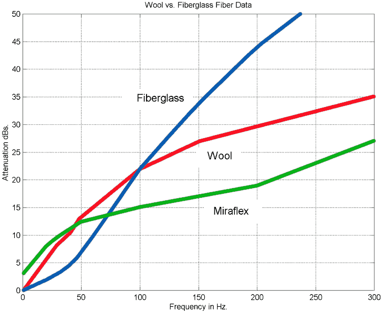
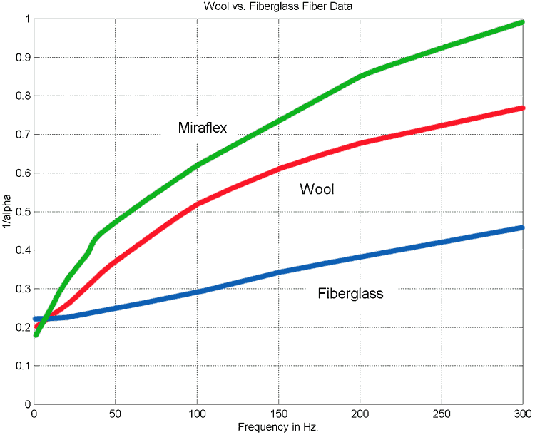
From the pages of Speaker Builder magazine, Bud Fried's product brochurs and measurement such as George and mine, I am convinced that the Bailey/Wright transmission line with long fiber wool stuffing is a non-resonant enclosure. It happens because the long fiber wool is a very effective sound attenuator starting at as low as 100-150 Hz and presents an infinite baffler type loading to the driver. That's why Bailey called his creation a "non-resonant" enclosure.
The difference between Bailey TL and an aperiodic enclosure is on how the back wave of the driver below 150 Hz is treated. The long fiber wool slows it down progressively (more air speed reduction as the frequency goes down) and makes the TL to become a half wave phase inverter at the driver free air resonant frequency. It creates a perfect argumentation of the bass without the ringing effect of a bass reflex or other vented design.
I try to explain how the Bailey TL works in layman's term. Leslie Bradbury developed one of the most elegant mathematics model for fiber filled enclosure. I tried to replicate Bradbury's calculation on a HP programmable calculator after I read the paper and found that I did not get the same numbers as he did in the paper. I found the typo when I went through the derivation of his equations and reconciled the calculation. I concluded that it was a typo made by the Journal of AES, not a mistake by Bradbury.
Through this process, I saw the beauty of Bradbury's work. The typo was a small, but critical one. In picture 1 is the original text in the AES Journal. In the definition of theta just under equation 4(b), both arctangent terms should be negative. The typo is missing the first "-" sign.
In order to perform numerical calculation, you need to convert the complex number in equation (3) into real and imaginery parts. Picture 2 shows how I duplicated Bradbury's derivation. You convert the complex numbers into polar form to do the division in equation (3). Then convert it back to real and imginery parts of equation 4(a) and 4(b) for the calculation. Very simple operation for students of linear algebra or engineering mathematics class. But the resultant equations of complex numbers are non-linear and do not lend themselves well to easy integration with vented box model using simple filter theory.


Yes, I understand that the Bailey and Bradbury works are NOT complete. They did not model how to couple the driver to the enclosure, thus, leaving the actual design as mostly empirical. The work by Bailey and Jastak (1973 Audio Amateur) filled an important gap.
Trying to model the TL enclosure as a resonant, vented box and changing the stuffing material to polyfill so that it can be coupled to a driver model is like cutting the foot to make the shoes fit.
Last edited:
I am convinced that the Bailey/Wright transmission line with long fiber wool stuffing is a non-resonant enclosure.
It can't be… it is using a quarter-wave RESONANCE to augment the bass.
It happens because the long fiber wool is a very effective sound attenuator starting at as low as 100-150 Hz and presents an infinite baffler type loading to the driver.
Nothing is very good at low frequencies;
If the line was acting as an infinite baffle there would be no output from the terminus. You keep contradicting yourself.
makes the TL to become a half wave phase inverter
That contradicts physics. It is open at one end so it is well-established that it is a quarter-wave resonator.
dave
Dave,
There is no point of continuing the argument. I did not do any research or design of the transmission line enclosure. Everything I said were quoted from the Bailey or Bradbury publication which you also have.
The Bailey line is a half wave length tube because the long fiber wool slows down the airspeed of the sound wave. Bailey and Bradbury provided plenty of analytical and empirical evidence of the half wave conclusion they made. If you do not want to believe them, it is your progative. Yes, a Dracon or polyester filled line is quarter wave length because they do not slow down the airspeed. It makes the line a resonant tube too.
Wavelength = airspeed/frequency
We are comparing apple (the Bailey LFW filled line) to orange (your polyfill line). Let's stop here.
Last edited:
I did not do any research or design of the transmission line enclosure.
I have been building & designing TLs since 1974. I am the guy behind t-linespeakers.org. I helped Martin with his initial presentation of his model I was at AES when Augspurger presented his paper/model. I understand them pretty well.
You seem to be stuck at Bailey.
dave
I have been building & designing TLs since 1974. I am the guy behind t-linespeakers.org. I helped Martin with his initial presentation of his model I was at AES when Augspurger presented his paper/model. I understand them pretty well.
You seem to be stuck at Bailey.
dave
Augspurger made the erroeous assumption that all fiber were created equal and chose polyester as his stuffing. He saw the fiber velocity term in Bradbury's paper but did not noticed that Bradbury argued that, in long fiber wool, the fiber velocity is very small and thus can be consider stationary. Compared to Bradbury's, Augspurger's paper was very poorly researched.
Trying to model the TL enclosure as a resonant, vented box and changing the stuffing material to polyfill so that it can be coupled to a driver model is like cutting the foot to make the shoes fit. That's what both Augspurger and Martin King did. Their models are easy to follow mathematically, but they did not account for the reactive component of the reaction of some fiber material such as fiber glass and long fiber wool.
There are many grades of wool. The fine one are expensive and more suitable for garments. I suspect that the ultra fine wool are indeed similar to fiber glass. Bailey's design specified the coarse wool meant for rug or other industry uses, which are stiff enough to slow down the airspeed by fluid dynamics effect. Bradbury's model beared out the result.
Yes, I am stuck with Bailey, good science and good sound. I am happy with it. I have no commercial interest to protect.
What do you think of the Ken Kantor blog on his fiber material research? Do you agree with Ken that fiber glass is more reactive and polyester is mostly resistive?
Last edited:
The speakers I refered to were first built around 1979.
Drivers, cross-over and wool were bought as a kit from UK (the source was advertised in WW).
They belong to a friend.
I rebuilt them 3-4 years ago for him (where the measurements are from).
I can not contribute any thing productive to the discussion btn Kei and Dave.
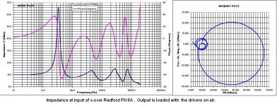
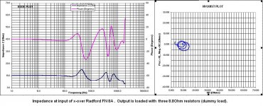
I realise now that I should have measured the impedance of the B139 on the unstaffed TL too.
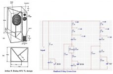
Regarding the initial post of onkyponk, I would encourage him to build the triangular TL of Baily. The bass is tight with weight, very good control, cabin is relatively easy to build.
Drivers
Tweeter: KEF T27 SP1032, B0779
Midrange: KEF B110 SP1003 C2079
Woofer: KEF B139 SP1044 C1579
x-over
Radford FN 8A (air core coils)
The attachments are for you onkyponk
The only deviation from the original plans is that the midrange had it’s own closed box ~150x150x150mm with lose glass fiber stuffing.
The x-over/speakers are not a very heavy load. An amplifier with a properly sized power supply drives them well. The difference will be noticed on the control of the bass.
George
Drivers, cross-over and wool were bought as a kit from UK (the source was advertised in WW).
They belong to a friend.
I rebuilt them 3-4 years ago for him (where the measurements are from).
I can not contribute any thing productive to the discussion btn Kei and Dave.
I realise now that I should have measured the impedance of the B139 on the unstaffed TL too.
Regarding the initial post of onkyponk, I would encourage him to build the triangular TL of Baily. The bass is tight with weight, very good control, cabin is relatively easy to build.
Drivers
Tweeter: KEF T27 SP1032, B0779
Midrange: KEF B110 SP1003 C2079
Woofer: KEF B139 SP1044 C1579
x-over
Radford FN 8A (air core coils)
The attachments are for you onkyponk
The only deviation from the original plans is that the midrange had it’s own closed box ~150x150x150mm with lose glass fiber stuffing.
The x-over/speakers are not a very heavy load. An amplifier with a properly sized power supply drives them well. The difference will be noticed on the control of the bass.
George
Attachments
-
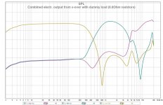 6 combined electr out from x-over with dummy load 8r8.jpg108.6 KB · Views: 121
 -
 5 Drivers on speaker.JPG141.1 KB · Views: 108
 -
 4 Drivers on air.JPG140.2 KB · Views: 123
 -
 3 Dummy load.JPG142.5 KB · Views: 170
 -
 2 Speaker.JPG100 KB · Views: 547
 -
 7 combined electr out from x-over with drivers on enclosure.jpg110.7 KB · Views: 142
Last edited:
George,
Thank you for sharing the Badford kit information. The sound you described is the same as I heard my home built Bailey, which is very different from any vented box design using polyester based fiber for stuffing. But I recognize the fact that many listener prefer the sound of a vented box design using polyester based fiber for stuffing.
The preference in sound is a very personal choice and nothing for argument. However, I will argue to the end of the world that a long fiber wool filled enclosure and a polyester filled one do not measure the same and do not sound the same. To me, Arthur Bailey designed a non-ringing bass enclosure that performed exactly as he described and Bradbury provided the scientific explanation why long fiber wool works differently in the enclosure.
You can see that "Bud" Fried accomplished the same sound character with his open cell foam filled speakers from his product brochurs. I met him and heard his product demonstration while I lived in Minnesota (US) in the 1970's. The legend was that Saul Marantz heard the speaker that Fried built for himself and encouraged Fried to get into the speaker business.
I like your quote ["Second Law is a bitch." - SY]. Who is SY anyway? (Yes, you can guess that I am a thermodynamics engineer in trade.) 😉
Who is SY anyway?
He is a very active member here
diyAudio - View Profile: SY
He is devoted to distilling a few drops of enthalpy out of this forum activities.
A great enemy of entropy growth.
If he bites you, run for a rabies vaccine.
George
Thank you very much for the replys , but so far I have decided I definatly want a separate woofer enclosure, with a simple sealed enclosure for the tweeters and mids. So far i have planned it to be about 2.6m long with a straight transmission line , no tapering, the Fs however is reported to be 25hz making a quarter wave length box 3.2m long, how much stuffing will I need to overcome this ? I'm choosing the module design for aesthetics and simplicity. Again I'm not familiar with the mathematics of building a box and I'm almost totally new to this.
Hi,
Rarely have I read such advanced nonsense about stuffing materials.
MJK clearly shows that its the density that matters mostly, and
polyfill, rather than cutting the foot to make the shoe fit, can
reproduce exactly the same curves as shown by LFW if its
density its suitably adjusted, LFW is simply not necessary.
Now the optimum impedance profile is not set in stone.
Neither is the distribution of stuffing of various density.
Pay your money, take a choice, on the amount of terminal
output, which always remains 1/4 wave, never becoming
the half wave nonsense unless the end is overstuffed
and begins to approximate a closed terminus.
Pontification that LFW is the cure of all ills is just that,
uniformative pontification, which Fried was fond of,
and ignores the design choices currently available.
MJK has found not much to like about Frieds "designs",
and the way they are claimed to operate is just wrong.
Here the claims about LFW versus other stuffing is just wrong.
Its a tedious old school method of presenting opinion as fact,
when your basically making your best guess as to the facts.
rgds, sreten.
Thank you very much for the replys , but so far I have decided I definatly want a separate woofer enclosure, with a simple sealed enclosure for the tweeters and mids. So far i have planned it to be about 2.6m long with a straight transmission line , no tapering, the Fs however is reported to be 25hz making a quarter wave length box 3.2m long, how much stuffing will I need to overcome this ? I'm choosing the module design for aesthetics and simplicity. Again I'm not familiar with the mathematics of building a box and I'm almost totally new to this.
Hi,
Have a look at :
http://www.quarter-wave.com/TLs/Alignment_Tables.pdf
http://www.quarter-wave.com/TLs/Alignment_Tables_Calculator_3_3_09.xls
For Basic TL alignments. However note that by modern standards
though the B139 can go low its excursion capability is pretty limp,
and the max SPL of a big TL for it will be somewhat restricted.
Depends on your mid treble efficiency and SPL whether that will be a limitation.
FWIW a B139 is ideal as a sub for low efficiency low max SPL small boxes.
rgds, sreten.
Last edited:
Hi,
Rarely have I read such advanced nonsense about stuffing materials.
MJK clearly shows that its the density that matters mostly, and
polyfill, rather than cutting the foot to make the shoe fit, can
reproduce exactly the same curves as shown by LFW if its
density its suitably adjusted, LFW is simply not necessary.
rgds, sreten.
If you can find any error in the mathematics or any hole in the test data in Leslie's Bradbury's paper, point it out to the whole world to see. If you do not understand the mathematics behind Bradbury's conclusion, don't call it "advanced nonsense about stuffing materials".
It is obvious that you do not understand the research that Ken Kantor and Robert White did either. I sent you those links. Are they also "advanced nonsense about stuffing materials" in your book?
Just for your information, Martin King never showed a bass response curve with the type of 6 dB/octave decay that is characteristic of transmission line speakers. The Dracon stuffing does not work because it cannot slow down the speed of sound in the tube.
Last edited:
a bass response curve with the type of 6 dB/octave decay that is characteristic of transmission line speakers.
The roll-off of a TL is anywhere between 6 dB (aperiodic or near) with little bass augmentation up to 24 dB/octave for a lightly stuffed line with maximum bass (and likely some ripple -- althou we have learned tricks to deal with those without just using brute force stuffing). 6 dB/octave is not a TL characteristic it is a fully aperioic characteristic (whether a TL or not)
dave
This driver sounded pretty good to me in a 70-liter closed box. Since you are a newbie, maybe there's no need to complicate things unnecessary ;-)
In my experience, perceived bass-quality depends a lot on the transition to midrange anyway.
In my experience, perceived bass-quality depends a lot on the transition to midrange anyway.
The roll-off of a TL is anywhere between 6 dB (aperiodic or near) with little bass augmentation up to 24 dB/octave for a lightly stuffed line with maximum bass (and likely some ripple -- althou we have learned tricks to deal with those without just using brute force stuffing). 6 dB/octave is not a TL characteristic it is a fully aperioic characteristic (whether a TL or not)
dave
I have not seen a transmission line enclosure in the Wireless world and Speaker Builder pages that do not show the 6 dB/octave character. It is probably because all those builder sticked with the long fiber wool stuffing.
Do you agree with Ted Jordan that a tight, non-ringing bass will have the 6 dB/octave character? I believe we are in agreement here.
Let's agree to disagree that you call the Martin King design transmission line and I call the Bailey enclosure transmission line.
I believe that we also agree that the Martin King TL will measure differently in impedance and response curves than the Bailey TL.
No, I am not saying that everyone should like the non-ringing bass best. Let's not get into the argument on what is the best. Many will consider it non-exciting and much prefer the bass from a vented enclosure with high slope of bass response decay. It is a matter of musical taste and personal choice.
Do you agree with Ted Jordan that a tight, non-ringing bass will have the 6 dB/octave character?
As in an aperiodic enclosure.
I call the Bailey enclosure transmission line.
Lines like this only represent a small part of TL "space"
I believe that we also agree that the Martin King TL will measure differently in impedance and response curves than the Bailey TL.
The Bailey TL is a subset of the Martin King TLs so i will disagree. Martin King provided us with a TL-modeler -- it is perfectly capable of modeling a Bailey-style near-aperiodic line.
No, I am not saying that everyone should like the non-ringing bass best.
If by non-ringing bass being 6 dB/octave roll-off then there is no useful output from the terminus.
I am not arguing which is best, that is very situation and goal dependent. I am just trying to counter the rote & mistaken position you are propounding.
dave
As in an aperiodic enclosure.
The Bailey TL is a subset of the Martin King TLs so i will disagree. Martin King provided us with a TL-modeler -- it is perfectly capable of modeling a Bailey-style near-aperiodic line.
You believe that Martin King can. It is quite different from that he did.
If by non-ringing bass being 6 dB/octave roll-off then there is no useful output from the terminus.
dave
Read the measurement and analysis that Bailey and Bradbury did, particularly page 167 of Bradbury.
bradbury said:The main idea behind a labyrinth type of cabinet is that at high frequencies, the fibrous material should damp out ALL internal resonances and present a constant resistive impedance to the rear of the loudspeaker cone. At these higher frequencies the reactive impedance should be very small. However, at low frequencies bass lift is supposed to be achieved by producing sound at the open end of the labyrinth that is in phase with the sound radiating from the loudspeaker directly. The effect should occur when the wavelength of the sound in the pipe is in the region of twice of the pipe length.
I believe Bradbury's description is technically very accuracy and he had both analysis and test data to show it. If you do not agree with his analysis or data, that's fine. Bailey also emphasize that his enclosure, while a physically quarter wave long tube in free air, is an effective half wave length pipe due to reduction in air speed.
The beauty of the Bailey idea is in its non-linear nature in the bass region. The sound pressure attenuation get less and less as the frequency goes down while the reduction of sound speed increases at the same time. Bradbury quantified the properties of the fiber that would produce the Bailey TL effect and showed not every fiber were the same.
I built the Bailey box and stuffed it with 0.5 lb/cuft of long fiber wool. I measured both a 6 dB/octave response curve and significant sound pressure at the terminus. My experience is NOT unique among Bailey line builders.
Last edited:
- Home
- Loudspeakers
- Multi-Way
- KEF B139b sp1044