Thanks Walter
Hi Walter,
Some time in the future, I want to build two mono block F5T V3, where I strongly consider using this kind of soft start, and yes I will use "panels with foil protection" again.
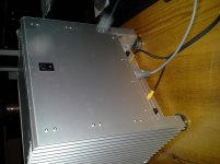
Reason for planning to build the Mono Blocks is that my current build has become too heavy (weight).
In my current build I have a combination of the www.diyaudio.com store soft start board (previous version) using thermistors instead of the resistors, and a AMB Laboratories DIY Audio, "ε24 power switch driver circuit", this worked great when the case was not complete and closed.
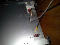
Now I have longer leads to the mono stable switch in the front of the case (Yes Andrew, I did twist the leads, 😉 ) and I sometime experience a switch off of the amp (pushing the switch turns on the amp immediately again).
I have read about fixes for the ε24 by using a larger elco, however I like listening to the amp more than taking it apart and rebuilding it 😀 at the moment.
I need to take the amp apart sometime in the future, I need to fix some resistors on the right channel board, had an issue biasing the Amp, (reading the following thread http://www.diyaudio.com/forums/pass-labs/207103-f5-turbo-builders-thread-80.html#post3313035 ) fixed this, but I left in some unclean soldered resistors.
Thanks again Walter for sharing your builds, very inspiring.
Grtz
Bert
Hi Bert,
The one you show at the pictures is a new one where the LED is at a header, which is nice...
Boards are working great if you replace the thermistors with two in series.
Walter
Hi Walter,
Some time in the future, I want to build two mono block F5T V3, where I strongly consider using this kind of soft start, and yes I will use "panels with foil protection" again.
Reason for planning to build the Mono Blocks is that my current build has become too heavy (weight).
In my current build I have a combination of the www.diyaudio.com store soft start board (previous version) using thermistors instead of the resistors, and a AMB Laboratories DIY Audio, "ε24 power switch driver circuit", this worked great when the case was not complete and closed.
Now I have longer leads to the mono stable switch in the front of the case (Yes Andrew, I did twist the leads, 😉 ) and I sometime experience a switch off of the amp (pushing the switch turns on the amp immediately again).
I have read about fixes for the ε24 by using a larger elco, however I like listening to the amp more than taking it apart and rebuilding it 😀 at the moment.
I need to take the amp apart sometime in the future, I need to fix some resistors on the right channel board, had an issue biasing the Amp, (reading the following thread http://www.diyaudio.com/forums/pass-labs/207103-f5-turbo-builders-thread-80.html#post3313035 ) fixed this, but I left in some unclean soldered resistors.
Thanks again Walter for sharing your builds, very inspiring.
Grtz
Bert
Last edited:
You are going to enjoy the F4 with the right pre!
I have a ba-3 built, and I have a SET with Russian sweep tubes, or I can try it with the Aikido. I think I'm going to like it being driven by the SET, but the proof of the pudding is where the rubber meets the road...

Hi Walter,
Some time in the future, I want to build two mono block F5T V3, where I strongly consider using this kind of soft start, and yes I will use "panels with foil protection" again.
Reason for planning to build the Mono Blocks is that my current build has become too heavy (weight).
In my current build I have a combination of the www.diyaudio.com store soft start board (previous version) using thermistors instead of the resistors, and a AMB Laboratories DIY Audio, "ε24 power switch driver circuit", this worked great when the case was not complete and closed.
Now I have longer leads to the mono stable switch in the front of the case (Yes Andrew, I did twist the leads, 😉 ) and I sometime experience a switch off of the amp (pushing the switch turns on the amp immediately again).
I have read about fixes for the ε24 by using a larger elco, however I like listening to the amp more than taking it apart and rebuilding it 😀 at the moment.
I need to take the amp apart sometime in the future, I need to fix some resistors on the right channel board, had an issue biasing the Amp, (reading the following thread http://www.diyaudio.com/forums/pass-labs/207103-f5-turbo-builders-thread-80.html#post3313035 ) fixed this, but I left in some unclean soldered resistors.
Thanks again Walter for sharing your builds, very inspiring.
Grtz
Bert
You are welcome!
I love this forum, all the ideas and all inspiration is shared all over the world. We all benefit 🙂
Hard way to soft start.
Sorry to plug into this thread with my issue, just noticed the boards were mentioned here similar to what I have (http://www.ebay.com/itm/Group-A-Amp...D&orig_cvip=true&rt=nc&_trksid=p2047675.l2557).
The problem with mines (I bought 2 of them) is that they both leak some Vac - after I turn on the main amp switch and before I trigger the start button to actually start the amp, I see ~90V of ac on the SS module output.
Just wonder if it's a kind of widely known issue in narrow circles or I just got junky boards. The other people seems have used similar boards with a success...
Soft start board? Self start board! 😀
Is the yellow X2 0.047uF capacitor OK?
You can try removing it, and put it back later...
Is the yellow X2 0.047uF capacitor OK?
You can try removing it, and put it back later...
Hah! Just was doing it, as figured out there is nothing else to leak through...
Looks much better now 🙂
Don't have 0.047 at the moment - would 0.1uF work ok?
Looks much better now 🙂
Don't have 0.047 at the moment - would 0.1uF work ok?
Last edited:
Yes, thanks - I have just tried, but replacement caused leak again (brand new x-rated caps from cpc).
What is this cap for - to avoid arcing relay contacts? Whay is it installed sequentially, not in parallel with mains (as a cap on the psu input as in Pass schematic)?
What is this cap for - to avoid arcing relay contacts? Whay is it installed sequentially, not in parallel with mains (as a cap on the psu input as in Pass schematic)?
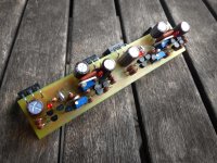
47nF across the L & N is for interference attenuation.Hard way to soft start.
Sorry to plug into this thread with my issue, just noticed the boards were mentioned here similar to what I have (http://www.ebay.com/itm/Group-A-Amp...D&orig_cvip=true&rt=nc&_trksid=p2047675.l2557).
The problem with mines (I bought 2 of them) is that they both leak some Vac - after I turn on the main amp switch and before I trigger the start button to actually start the amp, I see ~90V of ac on the SS module output.
Just wonder if it's a kind of widely known issue in narrow circles or I just got junky boards. The other people seems have used similar boards with a success...
It is not counted as leakage.
It's the AC current that passes through the capacitor when Mains AC voltage is applied.
If the 47nF is connected between Live In and Live Out, then again it is for interference attenuation. It will attenuate the voltage spike across the relay contacts when the contacts open, reducing the wear (sparking) of the contact surfaces and prolonging their life. All switch protectors that connect across the switch feed an AC current to the OUT terminal. When the OUT terminal has no load then the voltage approaches mains voltage. Once a significant load is applied the current through the capacitor depletes to virtually zero. This is normal for suppressed switches.
When the capacitor/s are L to E or N to E, then they need to be Y2 (for 240Vac). These too pass AC current, but this time it flows to the Protective Earth . This is referred to as earth leakage and does affect devices that detect earth leakage, eg. RCD, RCBO etc.
If you remove the attenuating capacitor, then the voltage spikes on the mains may affect the circuitry and may cause early failure.
Last edited:
...It is not counted as leakage.
...Once a significant load is applied the current through the capacitor depletes to virtually zero. This is normal for suppressed switches.
...If you remove the attenuating capacitor, then the voltage spikes on the mains may affect the circuitry and may cause early failure.
Thanks Andrew, good explanation, as always. Even predicting my next (probably, obvious) question about removing the capacitor.
Have no load yet to check it under the load (may try a 100W bulb, but have no any at hand at the moment).
Apologies for 'contaminating' this thread, I realise this stuff belongs more to PSU topics, it just happened to come across those soft-starters here, so just was curious if anyone had the same experience as me.
It is normal as the cap is across the live input and output, or in parallel with the relay for the reason Andrew outlined above. I don't remember the actual voltages i measured on mine but it was so low it really wasn't worth worrying about.
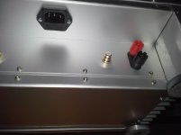

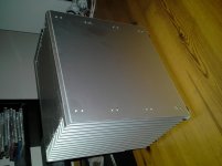
Here's a pic or two. Cubie 2. Should have a bunch more soon.
Good work my dear😀
- Home
- Amplifiers
- Pass Labs
- Pictures of your diy Pass amplifier