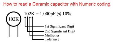
Ok now i see...This is the way most manufacturers list their capacitor sizes in their part numbers. It's the same as standard resistor bands work.
The first two digits are the size in pF. The third digit is the decade or multiplier band.
10 = 10pF. Add 8 zeros = 1000000000pF or 1000uF.
as 104=100nf/0.1uf
this 108uf confused me.
Thanks.
That is normal 'IEC' standard markings, the three digit code that is. I confused a good many when I began marking all my boards that way. It does lend a consistency to the marking scheme though, and that's why I like it.
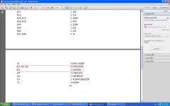
Another question is about U1 in the bom list.Something wrong is here.
Attachments
Last edited:
U1 is supposed to read ULN2003. I've got a couple bugs going on with Diptrace right now. Not saving random corrections is one of them.
When I mark caps like that I should be marking that as 108pF. Normally I would just mark that 108. I added the uF quickly before uploading the file.
When I mark caps like that I should be marking that as 108pF. Normally I would just mark that 108. I added the uF quickly before uploading the file.
Please confirm,U1=ULN2003,U2&U6=HCPL2530,U3=LM393U1 is supposed to read ULN2003. I've got a couple bugs going on with Diptrace right now. Not saving random corrections is one of them.
When I mark caps like that I should be marking that as 108pF. Normally I would just mark that 108. I added the uF quickly before uploading the file.
Thanks🙂
U1 = ULN2003
U2 = HCPL2530
U3 = LM393
U4 = LM7812
U5 = LM7805
U6 = HCPL2530
U7 = TC54VC3002EZB
IC1 = ATMEGA328
I1 & I2 = ASSR-V622-302E
U2 = HCPL2530
U3 = LM393
U4 = LM7812
U5 = LM7805
U6 = HCPL2530
U7 = TC54VC3002EZB
IC1 = ATMEGA328
I1 & I2 = ASSR-V622-302E
Valery, have you ever had problems with Diptrace merging nets together? I've had it happen a few times now and it's a huge pain to correct. In my latest DAC design it merged all my Digital and Analogue grounds together. Diptrace support told me to deselect "Connect Nets By Name" in the nets properties to correct it. I'm trying to figure out why they merged in the first place?
C1 is a decoupling cap for the Atmega328. It should be 100nF.
C3 and C4 are for the crystal. They should match whatever you selected for a crystal.
C3 and C4 are for the crystal. They should match whatever you selected for a crystal.
Ok ,mistake is mine.C1 is a decoupling cap for the Atmega328. It should be 100nF.
C3 and C4 are for the crystal. They should match whatever you selected for a crystal.
Sorry Jeff 😱The resistor network 4k7 is bussed or isolated type?
Bused.
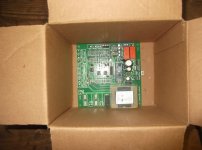
Pcb arrived today!
10 pieces+1 bonus.
Thanks Jeff.
Is there a bom somewhere?
Is it possible to buy a PCB from you?
I haven't any PayPal αccount.🙁Is it possible to buy a PCB from you?
Please PM me with your email address.Maybe we can find a solution.
There seems to be a few projects here as I was going through the thread. If I'm looking for a SSR speaker protection that I can use with my existing PSU which one should I use and is there PCBs available?
Heat sensors, soft start and other features are also welcome.
I usually never use speaker protection since I do not want to add distortion or anything between the amp and speakers but soon realized that with DC coupled amps it is quite dangerous, living on the edge... 😀
Thanks!
Do
Heat sensors, soft start and other features are also welcome.
I usually never use speaker protection since I do not want to add distortion or anything between the amp and speakers but soon realized that with DC coupled amps it is quite dangerous, living on the edge... 😀
Thanks!
Do
There seems to be a few projects here as I was going through the thread. If I'm looking for a SSR speaker protection that I can use with my existing PSU which one should I use and is there PCBs available?
Heat sensors, soft start and other features are also welcome.
I usually never use speaker protection since I do not want to add distortion or anything between the amp and speakers but soon realized that with DC coupled amps it is quite dangerous, living on the edge... 😀
Thanks!
Do
Hi Do,
This is actually the same project evolving 🙂
Here is the latest version heavily tested and built by a number of members:
Compact PCB by Jeff Wilhelm with SS relays
Somebody produced a bunch of PCBs here recently.
Gerbers are also available if you want to order yourself.
I have attached the board description I did some time ago - it shows an older PCB with electromagnetic relays, but the functionality is exactly the same, providing the soft-start as well as DC offset, over-current, over-temperature and AC failure protection, with certain redundancy, as well as status indication with a single LED.
I will send the firmware to your e-mail if you would like to build it.
Let me know if you have questions 😉
Cheers,
Valery
P.S. It has saved a number of speakers already 😉
Attachments
Last edited:
This "alien" project just saved my ar$e again. Went open loop on a
72v rail "super amp". The 70V DC transient did not even move the woofer
a CM.
This is the best 'invention" in all DIY land !!
- Heed my words -
PS - this is so far ahead of chinese ebay offerings - the next level !!
OS
72v rail "super amp". The 70V DC transient did not even move the woofer
a CM.
This is the best 'invention" in all DIY land !!
- Heed my words -
PS - this is so far ahead of chinese ebay offerings - the next level !!
OS
Last edited:
My poor Quatre
My Quatre could of used this a long time ago.🙁 Is there a zip file of everything (gerber, code, bom, etc.) somewhere for the through-hole version? Anyone selling PCB?
Thanks,
MI
My Quatre could of used this a long time ago.🙁 Is there a zip file of everything (gerber, code, bom, etc.) somewhere for the through-hole version? Anyone selling PCB?
Thanks,
MI
My Quatre could of used this a long time ago.🙁 Is there a zip file of everything (gerber, code, bom, etc.) somewhere for the through-hole version? Anyone selling PCB?
Thanks,
MI
You might of lucked out. I have 4 of the new versions and the first version
(below).
That one needs a new home .... 🙂
It was working in my amp , new versions are much smaller.
OS
Attachments
- Home
- Amplifiers
- Solid State
- How to build a 21st century protection board