The changes in question at most reduce the open loop gain by just a few dB, and should be sufficient to ensure constant (if somewhat lower) gain out to at least 20kHz. Solid state amplifier designers have reported similar findings in the design of VAS in the past. (Walter Jung, Matti Otala amongst others.)
Matti Otala was generally full of it - especially regarding the role of nfb and openloop bandwidth on the generation of TIM - just plain wrong.
If the changes in question reduced the loop gain of your regulator by just a few dB (to bring the open loop bandwidth out to 20kHz), then your regulator already had an openloop bandwidth nigh on 20kHz anyway.
Did you actually measure the loop gain, 20Hz -20kHz?
Last edited:
Hi GK,
I actually meant to reply last night, but it took a while to dig through my old notes (18+ yrs old) and when I finally replied the site was doing server maintenance, so in a sense you could say the "server ate my reply." 😀
Anyway here is what I could find after all of these years (seems like a revisit with my current much improved test gear might be worth while):
The error amplifier gain was ~46dB and the measured open loop bandwidth into about 20pF of capacitance was dc - 20kHz -0.2dB based on the limitations of test equipment available this seems reasonable. (I did a quick sym and got results that corroborated those measurements. ) The older version made it to somewhere around 12kHz but IMO might have had some other issues relating to insufficient transconductance due to lower plate current.) The circuit in question was a cascode error amplifier based on the 12AX7A which is not a particularly good choice for this duty for reasons you already know, (but it was readily available at the time new, when many others weren't and could operate without incident at the required voltages) quiescent operating point typically was 0.8mA - 1.2mA , (test at ~0.8mA) grid of upper cascode fixed ~100V above the cathode of the lower cascode, and a plate load resistor of 162K to a 400V supply.. That's it in a nutshell - in the actual circuit there is a 100V (sometimes a little higher) bootstrapped (from the output) zener reference on the cathode of the lower cascode, feedback to the lower cascode grid, fixed bias on the upper grid typically 100 - 150V above the lower cascode cathode, a plate resistor which is connected to the filtered screen supply for the pass element which is typically at 150 - 200V higher than the output voltage.
Closed loop gains run from <10dB to 14dB max. (300 - 500V out depending on application)
Typical output capacitors are in the 10uF range (film type) which generally should dominate the output impedance above a few hundred Hz to a couple of kHz depending on the regulator output impedance. (This has always left me wondering in conjunction with the comments about open loop bw.)
It works well and there are dozens of them in existence some now 20+ yrs old, still working.
Last edited:
Typical output capacitors are in the 10uF range (film type) which generally should dominate the output impedance above a few hundred Hz to a couple of kHz depending on the regulator output impedance. (This has always left me wondering in conjunction with the comments about open loop bw.)
Well this is a regulator with a rather high output impedance. It is typical to frequency compensate such a basic tube regulator that has a low loop gain with an output shunt capacitor. The capacitor provides a dominant pole roll-off to the open loop response (well below 20kHz in your case), in conjunction with the regulators output impedance.
However, this only works with basic regulators having a low loop gain due to the fact that a high loop gain would lower the output impedance too much, pushing the dominant pole frequency out too high and leading to instability.
Lowering the loop gain in this case reduces the regulators bandwidth!
🙄
Last edited:
And then you start to worry about the sound of the regulator transistors, regulator caps, etc.
Double work.
It seems people can do perfectly without them.
And if they improve the sound how is it that so little people have noticed it?
I remenber Gizmo and.....Berning.......and who else?
Actually, I use all tube (aside from SS filament regulators), including the voltage reference, regulation for all my line level stuff. Not a speck of sand near the audio path after the rectifier. I can definitely hear all that. I also considered using supply regulation for my DC Coupled OTL, but I found that some serious power supply overdesign using all polypropylene caps except for the output stage which is merely bypassed with polypropylene, a fully balanced topology & providing feedback correction for output stage supply ripple worked well enough. so this stereo OTL uses only one raft of parts instead of two rafts and is very inefficient rather than abysmally inefficient😀
Last edited:
Pentode followers can provide source impedances which are sub 1 ohm with modest levels of feedback.. Just how low do you really think the output impedance of an LM317 is at 10kHz? Hint: it's not really that low particularly if Cadj is omitted.
And the regulator is completely stable without the output capacitor.
Note that I did say "error amplifier" in my previous comments.
Bye 😀😀
With a maximum loop gain of only 14dB (5!) I'm not surprised that it is stable without an output capacitor. For a sub 1 ohm output impedance closed loop, that would require sub 5 ohm open loop output impedance (possibly obtainable with one of those magic pentodes with super high gm).
What does an LM317 have to do with anything? You obviously fail to comprehend how that output capacitor defines the open loop bandwidth, making your =>20kHz OL BW theory completely bunk.
A pain to read your posts GK with that pic hanging there.
Is that a punk attitude?
Moderator how can I stop ugly avatars from showing up?...I was relaxing until that thing disturbed my peace.😀
Is that a punk attitude?
Moderator how can I stop ugly avatars from showing up?...I was relaxing until that thing disturbed my peace.😀
With a maximum loop gain of only 14dB (5!) I'm not surprised that it is stable without an output capacitor. For a sub 1 ohm output impedance closed loop, that would require sub 5 ohm open loop output impedance (possibly obtainable with one of those magic pentodes with super high gm).
What does an LM317 have to do with anything? You obviously fail to comprehend how that output capacitor defines the open loop bandwidth, making your =>20kHz OL BW theory completely bunk.
Note that I deleted my previous post before I saw your response. Thank you for being so kind. 🙄
In fairness to me I was reporting the observations of others, it's actually not my theory, secondly I stated in at least one post that I couldn't demonstrate an audible difference. Also I thought it was clear I was suggesting experimentation, I didn't think I was being dogmatic about it.
Here's my take on your extremely uncharitable comments. I' m glad you are so good at quoting the text book, here are the results of some analysis that actually clearly proves your point.
Your math is in error, since the open loop gain is actually 46dB, the closed loop gain 10 - 14dB depending on the voltage required giving a loop gain margin of 32 - 36dB. This gives an effective output impedance reduction of 40 - 63 amongst other things based on the available feedback margin.
I measured the error amplifier only - stating that clearly and pleasantly and did not talk anywhere about the closed loop bandwidth of the regulator. A pentode connected pass element has negligible miller capacitance, Cin is about 16pf so figuring 20pF with strays is not too unreasonable and this would result in an open loop bandwidth of ~45 - 50kHz (-3dB - what we care about right?) So even at 50kHz there is roughly 30dB of loop gain margin..
Closed loop without the output capacitor results in closed loop bandwidth theoretically in the region of 2 - 3MHz. I have NOT measured this and would not expect to actually see that achieved in practice.
The output pole with a 10uF cap and 1 ohm source impedance is nearly 16kHz. Even a high transconductance power pentode follower like the EL34 will not have a source impedance much lower than 90 ohms or so (assuming 1/gm) so figure the closed loop output impedance best case might approach 1.5 ohms, giving a dominant pole of right around 10.6kHz with a 10uF output cap.
So technically YOU ARE CORRECT with an ideal capacitor and that also explains why it is stable with a 10uF cap on the output.
(The relevant poles are sufficiently staggered to meet stability criteria.)
Edit: The capacitor's ESR in this case will significantly affect the point at which capacitance becomes the dominant factor in output impedance, and given the scenario outlined above it would just take a couple of ohms for that to occur above 20kHz or not at all. So maybe my comments were not as irrelevant as you maintain.
Last edited:
Note that I deleted my previous post before I saw your response. Thank you for being so kind. 🙄
In fairness to me I was reporting the observations of others, it's actually not my theory, secondly I stated in at least one post that I couldn't demonstrate an audible difference. Also I thought it was clear I was suggesting experimentation, I didn't think I was being dogmatic about it.
Here's my take on your extremely uncharitable comments. I' m glad you are so good at quoting the text book, here are the results of some analysis that actually clearly proves your point.
Your math is in error, since the open loop gain is actually 46dB, the closed loop gain 10 - 14dB depending on the voltage required giving a loop gain margin of 32 - 36dB. This gives an effective output impedance reduction of 40 - 63 amongst other things based on the available feedback margin.
I measured the error amplifier only - stating that clearly and pleasantly and did not talk anywhere about the closed loop bandwidth of the regulator. A pentode connected pass element has negligible miller capacitance, Cin is about 16pf so figuring 20pF with strays is not too unreasonable and this would result in an open loop bandwidth of ~45 - 50kHz (-3dB - what we care about right?) So even at 50kHz there is roughly 30dB of loop gain margin..
Closed loop without the output capacitor results in closed loop bandwidth theoretically in the region of 2 - 3MHz. I have NOT measured this and would not expect to actually see that achieved in practice.
The output pole with a 10uF cap and 1 ohm source impedance is nearly 16kHz. Even a high transconductance power pentode like the EL34 will not have a source impedance much lower than 90 ohms or so (assuming 1/gm) so figure the closed loop output impedance best case might approach 1.5 ohms, giving a dominant pole of right around 10.6kHz with a 10uF output cap.
So technically YOU ARE CORRECT with an ideal capacitor and that also explains why it is stable with a 10uF cap on the output.
(The relevant poles are sufficiently staggered to meet stability criteria.)
Edit: The capacitor's ESR in this case will significantly affect the point at which capacitance becomes the dominant factor in output impedance, and given the scenario outlined above it would just take a couple of ohms for that to occur above 20kHz or not at all. So maybe my comments were not as irrelevant as you maintain.
I didn't notice that you deleted your post while I was typing. I read your previous post quickly (doing other things ATM) and misread about the closed loop (10-14dB) vs the loop gain.
That doesn't make much difference anyway. Your 10KHz bandwidth given by 1.5R/10uF is the closed loop BW of the regulator (the open loop BW is much less - ~180Hz for your example).
Regarding the output capacitor ESR, that is a seperate issue, but is one of the reasons why a capacitor at the output cannot be relied upon for frequency stabilisation in a regulator employing too much loop gain (gain margin is limited by Zout/ESR). At the other end of the spectrum (high loop gain) an output capacitor becomes a destabilising factor.
You made no distinction about bandwidth of the error amplifier alone, as opposed to the entire regulators open loop bandwidth when you wrote:
"The changes in question at most reduce the open loop gain by just a few dB, and should be sufficient to ensure constant (if somewhat lower) gain out to at least 20kHz. Solid state amplifier designers have reported similar findings in the design of VAS in the past. (Walter Jung, Matti Otala amongst others.)"
Last edited:
a pain to read your posts gk with that pic hanging there.
Is that a punk attitude?
Moderator how can i stop ugly avatars from showing up?...i was relaxing until that thing disturbed my peace.:d
😀😀
Last edited:
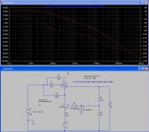
Here is a quick regulator (loop gain) sim to demonstrate what I'm going on about.
I've used a 6L6 connected as a triode (low gm) for the series pass element and just a NPN transistor for the error amplifer. The loop gain is just a little under 33dB
The first screen shot shows the loop gain and phase with no output capacitor. The open loop bandwidth is defined by the error amplifier, which begins rolling off pretty early (5-6kHz) with the large 200k load resistor.
The second screen shot shows what happens when a 10uF capacitor is added to the output.
The open loop bandwidth now starts to roll off very early (about 35Hz) due to the pole formed by the 10uF capacitor along with the high output impedance of the triode series pass element. This is now the dominat pole, the loop gain now going through unity at approximately 1.6kHz with a phase marging of ~80 degrees.
Note than in the first case (without the capacitor) the regulator is stable, but this is only because the current-starved error amplifier has a rather low bandwidth.
Attachments

Last edited:
I just used an idea cap because at these frequencies and loop gain the ESR/ESL makes absolutely no difference.
The tube series pass element has a 'resistance' of about 450 ohms. Suppose the cap is an unrealistically crappy one with an ESR of 0.5 ohms.
450/0.5 = 900 = 59dB attenuation.
That's still greater than the loop gain of 33dB by a more than adequate margin.
The tube series pass element has a 'resistance' of about 450 ohms. Suppose the cap is an unrealistically crappy one with an ESR of 0.5 ohms.
450/0.5 = 900 = 59dB attenuation.
That's still greater than the loop gain of 33dB by a more than adequate margin.
Last edited:
For my line level tube regulators I have used miniature dual triodes (low mu/hi mu) & voltage ref tube such as a 5651 or OA2 to conserve real estate and power. To lower output impedance to the sub 1 ohm range (excluding the effect of any capacitors that are at the output), I have added a positive current feedback scheme. I have also found a simple modification that lets me significantly improve input rejection - in the case of my preamp, that can be optimized with a potentiometer. Subjectively, I felt the latter gave an improvement in SQ comparable to regulating the AC to the preamp or 'holographic' processor with a sinusoidal ferroresonant transformer.
6AS7-6SJ7-0A3 VOLTAGE REGULATOR.
HI,
HAVE ANY P. C. BOARD?
I WANT TO PURCHASE 10 BOARD.
REGARDS,
ASHBY
HI,
HAVE ANY P. C. BOARD?
I WANT TO PURCHASE 10 BOARD.
REGARDS,
ASHBY
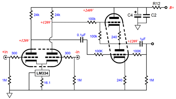
I'm sorry to revive more than a year old thread, but I need a tube regulator for my DAC output. The circuit is known as the unbalancer:
My power supply is 2*(EZ81-> C1 ->LCLCLCRC ); C1=10uF, L=5H, C=4uF, R=300 C->non electrolytic. The cathode follower part is a current amplification part, so I guess regulation isn't much needed there. But what about the anode followers? The signal is preamped there, so a low noise shunt regulator would do good.
The problem is I have space for only one tube per channel on my chassis. Would something like this reg do good?
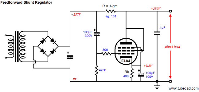
Last edited:
First of all, Thanks for all the help so far.
Here is a new schematic based on Kevin’s recommendations:
1. Pentode Plate voltage from the Raw B+ via an additional RC filter
2. G2 voltage via a voltage divider to ground, with the lower resistor bypassed with 10uf
3. G1 voltage via voltage divider (pot removed)
4. .47uf cap removed from the 0A3
It will be interesting to see if the Z-out of this regulated PSU is any better than the others I tested.
Stay tuned.
HI,
I am building the 6AS7 6SJ7 voltage reg.
from the 514 scope
http://bama.edebris.com/manuals/tek/514d/
The +225 regulator with the differintal 12AX7.
Regards,
Ashby
Hi Sgerus,
I did mine 300B SE years ago with tube power supply ( 6550 series pass tube ) - it is worth-it sound wise. It gives more refined sound than just caps & resistors/chokes, but it needs higher voltage on input to work properly...
6AS7 is also good candidate & cheaper one...
Max
I did mine 300B SE years ago with tube power supply ( 6550 series pass tube ) - it is worth-it sound wise. It gives more refined sound than just caps & resistors/chokes, but it needs higher voltage on input to work properly...
6AS7 is also good candidate & cheaper one...
Max
Attachments
GK, Kevin,
I just finished testing the V-Reg with the CCS
The results are amazing; you can hear the difference, no question about it.
The sound is sharper and more detailed than ever, and I'm setup in the basement on the cheap speaker!
Here are some of the details, I'll upload the schematic tomorrow.
3mA CCS for the plate of the pentode
(so now the pentode is operating at the “typical” value)
20mA CCS for the 0A3
With some on my earlier experiments, the 0A3 would flicker at 20Hz.
The 20mA CCS took care of that!
This setup allows the B+ to range from 258V to 360V
And the Z-out…….. .15R at 20Hz
Thank You
Sgerus,
I realize this is quite an old thread, but how and what kind of equipment did you use to measure the Z-out down to .15 ohms at 20Hz?
TYVM,
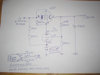
Hi Max, could you post your KT-88 (6550) schematic? I want to regulate my b+ for my 300B monos. I tried several MOSFET regs, they sound thick, mushy, complete loss of 3D stage and transistor like nervous highs. Bass is also detached from the rest of the music. Great loss of textures in the mids. If you put even 1 transistor in your rig then it will sound like ****. BTW, EL84 sound better as series reg than EL34 (I hate the sound of this tube).
Hi HornTube,
Uh ah, that was some 10-15 years ago... I searched for drawing but could not find it so I draw new one. I'm not sure if it is 100% same as I used for my amp but it is close enough for rough start, please experiment on breadboard before actually fitting in your amp. Make sure you use separate filament transformer for each regulator tube!
Instead of 6550 ( KT88 ) I also used 6L6 ( for pre-amp and/or screen regulation ) and parallel connected 6AS7G ( 6080 ) for another 300B amp with great success, please be aware of a very high voltage input needed for regulator to even work ( approx. ± 550-600 volt DC ) and place a fuse before regulator just in case something goes wrong!
Regards,
Attachments
- Status
- Not open for further replies.
- Home
- Amplifiers
- Tubes / Valves
- Tube Voltage Regulator, Is it worth the effort?