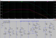
That is an incredible result with the cascode circuit. I seriously doubt that my instruments are up to such a delicate measurement, as it would involve the measurement of incredibly tiny voltages / currents, in fact could any equipment measure this assuming that it could actually be built to operate as in the simulation?
Actually I'd have expected better of the third circuit, the simpler cascode one, though perhaps it is relatively superior to the simple 1 bjt current source
Gordon.
The simple cascode is indeed much better than the simple one transistor current source: 7.9 Meg / 790 kOhm.
Have a look at the Keithley website. They can measure TerraOhms...
Its not difficult to measure Gigaohms, at least at DC.
Attachments
Its not difficult to measure Gigaohms, at least at DC.
Udok, what do you think of my proposal in post#138 for measuring DC resistance of a CCS?
I'm going to try it soon as AndrewT for one, is interested to know the result of this measurement.
Last edited:
Hello, Try it out and compare the results to the other circuit with the OPAmp at 1kHz.
Both should give the same result.
Greetings,
Udo
Both should give the same result.
Greetings,
Udo
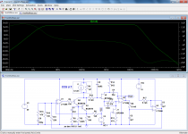
Here is an idea for an alternative measurement strategy: the CCS under test is included in a µ-amp, whose gain is determined by the source's dynamic resistance.
In practice, the load is a kind of gyrator, to make the servoing automatic.
Here is how it could look (it is simplified: for an easy and comfortable use, some additions would be required).
The heart of the circuit is a "metrological grade" CCS, built around U1, Q1 and Q2.
It is steered by an integrator, U3, via a very high impedance bootstrapped buffer, J2 U2.
The measurement stimulus is injected as a perturbation of the CCS via the injection resistor R6.
The gain is simply the ratio of the CCS resistance to R6, in this example 20dB.
Since the loop parameters vary with its gain, hence with the CCS resistance, the bandwidth is also modified.
For resistances around 10 Meg, the bandwidth is that of audio, it is somewhat extended with 1Meg, and reduced to 30 ~ 2000Hz for 100Meg.
In a practical implementation, this could be compensated to some extent.
Here, the schematic is drawn for positive-referenced CCS's, but it could be inverted for negative ones
Attachments
Here is an idea for an alternative measurement strategy: the CCS under test is included in a µ-amp, whose gain is determined by the source's dynamic resistance.
In practice, the load is a kind of gyrator, to make the servoing automatic.
Here is how it could look (it is simplified: for an easy and comfortable use, some additions would be required).
The heart of the circuit is a "metrological grade" CCS, built around U1, Q1 and Q2.
It is steered by an integrator, U3, via a very high impedance bootstrapped buffer, J2 U2.
The measurement stimulus is injected as a perturbation of the CCS via the injection resistor R6.
The gain is simply the ratio of the CCS resistance to R6, in this example 20dB.
Since the loop parameters vary with its gain, hence with the CCS resistance, the bandwidth is also modified.
For resistances around 10 Meg, the bandwidth is that of audio, it is somewhat extended with 1Meg, and reduced to 30 ~ 2000Hz for 100Meg.
In a practical implementation, this could be compensated to some extent.
Here, the schematic is drawn for positive-referenced CCS's, but it could be inverted for negative ones
Elvee,
From what I can gather with my limited knowledge base, it is basically an amplifier using the CCS under test as a high impedance load and by measuring the gain of this amplifier then the impedance of the CCS @ AC can be calculated, some of the finer points are lost on me but that seems to be the just of it, yes?
BTW, I haven't given up on this undertaking, my priorities have by neccesity had to change for now. I do have every intention of returning to this project ASAP.
Gordon.
Yes, that is how it works: it is based on the dual/complementary principle of that you have used so far: instead of applying a voltage to the DUT and measuring the (tiny) resulting current, it applies a small current and measures the resulting voltage.Elvee,
From what I can gather with my limited knowledge base, it is basically an amplifier using the CCS under test as a high impedance load and by measuring the gain of this amplifier then the impedance of the CCS @ AC can be calculated, some of the finer points are lost on me but that seems to be the just of it, yes?
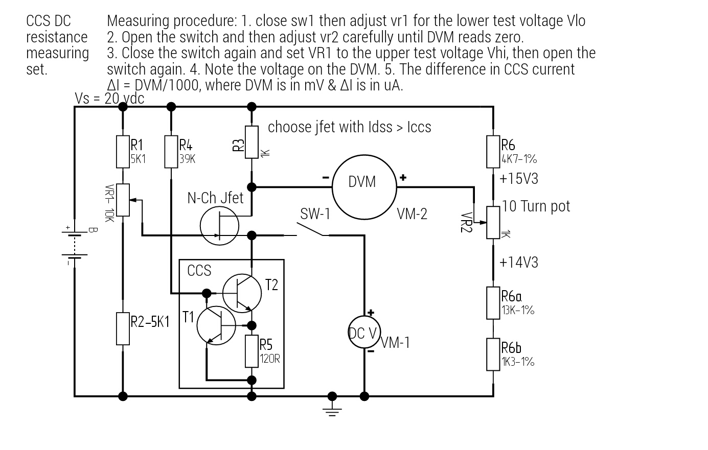
I have carried out a quick test on the DC resistance of the 5mA 2 transistor CCS using a bridge method similar to what I suggested earlier, see attached.
I'm not at all convinced of the validity of the result; 1.48M, which is considerably lower than the AC test. Notably I couldn't get DVM-2 to settle, it kept drifting up and down. Not sure if this is due to Vcc fluctuations, noise, him pickup or component temp coefficients, any suggestions are very welcome.
Gordon.
Attachments
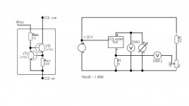
Now looking at my circuit again, I think it is probably flawed. I have neglected to include a resistor between the variable voltage source and the CCS. I'm not sure if this is the cause of the error, can anyone advise?
Now I am going out to enjoy the sun as its going to be raining tomorrow. Will probably be back on later today.
Gordon.
Now I am going out to enjoy the sun as its going to be raining tomorrow. Will probably be back on later today.
Gordon.
That does not look right.
The load and any variation of the load must be applied to the top right of the CCS.
The bottom is always fixed at -ve supply.
The top left is always fixed at +ve supply.
Add a load to the top right, say 1k0 resistor.
Attach a second variable resistor between the +ve supply and the 1k0 load resistor. Try 10k VR
The supply voltage must be Iccs*Rload + Iccs*VR + Vccsmin. This will come to about 12V per mA of Iccs, i.e. a 2mA ccs will require ~24Vdc.
The Vdrop across the 10k will be ~20Vdc, The Vdrop across the 1k0 load will be 2Vdc, the Vdrop across the CCS will be ~2V. The total comes to ~24Vdc.
Turn the variable resistor up to max. Measure the current through the load.
Turn the variable resistor down a bit. Measure the current through the load.
Turn the variable resistor down a bit more. Measure the current through the load.
Repeat this until the variable resistor is down to zero ohms.
Select an adjacent pair of settings/measurements. Calculate delta Iload
The impedance will be different through the range of CCS voltage drop. It will probably be highest (smallest change in I between adjacent measurements) when the Vccs is highest.
I needed your diagram to explain my DC method.
I see your Iccs is ~5mA, change the resistor load to ~390r and the VR to 5kVR to get your supply to a reasonable voltage >=29Vdc.
Last edited:
Thank you very much AndrewT for your detailed reply. Actually my original idea was along similar lines. I seem to be getting contradictory advice or perhaps I am missing something.
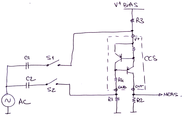
This was my original proposal for carrying out the DC measurement:
http://www.diyaudio.com/forums/attachments/solid-state/477111d1428835080-how-do-you-calculate-impedance-current-source-bridge-method-measuring-ccs-dc-resistance.jpg
VR1 performs the function of your proposed VR, but in a way that a measurement can be taken at the drain of the cascode transistor ( the jfet ) to prevent any loading on the CCS by the measuring circuit. The purpose of the DC bridge is to facilitate the measurement of the relatively tiny changes in CCS current due to fluctuations in its load.
I am going to try this method first, then I will try Andrews suggested method and see how they both compare.
It is going to be raining at the weekend so I'll be indoors and can undertake these measurements then.
Gordon.
What multimeter do you use for your measurements?
Some cheep bench top multimeters make troubles if the minus (-) input is not ground referenced.
Greetings, Udo
Some cheep bench top multimeters make troubles if the minus (-) input is not ground referenced.
Greetings, Udo
What multimeter do you use for your measurements?
Some cheep bench top multimeters make troubles if the minus (-) input is not ground referenced.
Greetings, Udo
I will need to check Udo, I'm not in my workshop just now. The bench meter is made by a company called EZ, I don't know that much about the company. The basic DC accuracy is quite good as I remember it, but I'll need to find the exact model.
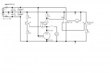
I am working on a scheme that uses an instrumentation amplifier ina131, with +/- 15 volt supplies. The output will be ground referenced so if the problem is due to the meter not working properly, then this solution should get round this issue. I will post the schematic later when I am happy with it.
I haven't carried out any more measurements yet as there was a massive backlog of housework needing done. Having a great big clear out!
Gordon.
Here is my latest proposal for measuring the DC resistance of a CCS. It uses a bridge again but also an instrumentation amplifier ina131 to provide a ground referenced output. The circuit uses symmetrical +/- 15 volt supply with the CCS placed between the gnd and -ve rails.
I would encourage all readers to post any questions or comments regarding this proposal.
Gordon.
BTW I intend to use a modified version of this scheme to make further ac measurements in due course.
I would encourage all readers to post any questions or comments regarding this proposal.
Gordon.
BTW I intend to use a modified version of this scheme to make further ac measurements in due course.
Attachments
Udo, here is a link to the model of bench meter I am using:
EZ Digital DM-441BT Digital Multimeter Bench Type, Frequency EZ Digital DM-441B, DM441B, DM 441B | TEquipment.NET
Gordon.
EZ Digital DM-441BT Digital Multimeter Bench Type, Frequency EZ Digital DM-441B, DM441B, DM 441B | TEquipment.NET
Gordon.
I'll try this method.
Did you ever try this method peufeu?
Last edited:
Udo, here is a link to the model of bench meter I am using:
EZ Digital DM-441BT Digital Multimeter Bench Type, Frequency EZ Digital DM-441B, DM441B, DM 441B | TEquipment.NET
Gordon.
Hi Gordon,
It seems that your multimeter cannot measure AC below 45 Hz. Maybe this is the reason why your low frequency results differ.
The inductors in your new circuit do not cause harm, but they are useless for low frequency regulation. Use a LM317 or similar... as you are only interested in audio frequencies, you can forget about the inductors...
I don't understand why you use the complicated INA approach? Is there any advantage in comparison to the older circuit? In the older circuit you get the ground reference for free..
In reality you are not interested in the CCS DC impedance... its the AC impedance at 20 Hz - 20 kHz which counts.
Greetings,
Udo
Did you ever try this method peufeu?
Didn't have time, too much stuff do do 😉
On this kind of stuff the simulator gives pretty good results though...
My reasoning has been guided by my belief that the DC impedance of the CCS is the same as the very low frequency impedance of the CCS....................In reality you are not interested in the CCS DC impedance... its the AC impedance at 20 Hz - 20 kHz which counts.
...............
Maybe this is not a good assumption.
What is the "shape" of a typical CCS impedance vs frequency curve?
My reasoning has been guided by my belief that the DC impedance of the CCS is the same as the very low frequency impedance of the CCS.
Maybe this is not a good assumption.
What is the "shape" of a typical CCS impedance vs frequency curve?
Andrew, I think that it's akin to a lowpass filter, roughly determined by the base collector capacitance of the transistor, however using the same technique as the cascode amplifier, the cascode CCS offers a fair degree of isolation from the effects of this capacitance. There might be more to it than that as I'm not an EE so still have much to learn.
I'm doing some more ac testing today with another set up using split power supply. I'm getting some unexpected results so I'm going to go back and look at it. The good news is for those following this saga, is that I have kept notes on my investigation and will share in due course!
Gordon.
This is the circuit set up used today. One issue has been identified but as yet I'm not clear on the cause;
At lower frequencies < 3300 Hz the output appears relatively flat, however a very low frequency component has been found at the output of the 5534. I have disconnected the I/p of the amplifier and grounded it and the ~0.4Hz low frequency component dissapears, so it seems to be coming from the CCS and connected items, at the moment I am at a loss to explain this, can anyone else help?
At lower frequencies < 3300 Hz the output appears relatively flat, however a very low frequency component has been found at the output of the 5534. I have disconnected the I/p of the amplifier and grounded it and the ~0.4Hz low frequency component dissapears, so it seems to be coming from the CCS and connected items, at the moment I am at a loss to explain this, can anyone else help?
Attachments

- Status
- Not open for further replies.
- Home
- Amplifiers
- Solid State
- How do you calculate impedance of a current source?