A good standard PS regulator will do it, but wiring should not be too long.
The CCS circuit is a standard textbook one.
It has improved impedance due to negative feedback.
The greater R2, the greater is the feedback and the output impedance.
Even the standard version with moderate R2 has a negative output impedance at higher frequencies. This can cause oscillations...
A current source instead of R2 needs careful testing. Better to use a cascoded current source for good HF impedance. At higher f the impedance is limited by Cbc.
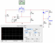
The -5 dB PSRR means that 1mVolt of PS ripple is seen at OUT as 0.56 mV.
The signal due to CCS at OUT is about 3 mV.
The voltage drop at R3 and R9 should be about 5 Volt.
Udo
The CCS circuit is a standard textbook one.
It has improved impedance due to negative feedback.
The greater R2, the greater is the feedback and the output impedance.
Even the standard version with moderate R2 has a negative output impedance at higher frequencies. This can cause oscillations...
A current source instead of R2 needs careful testing. Better to use a cascoded current source for good HF impedance. At higher f the impedance is limited by Cbc.
The -5 dB PSRR means that 1mVolt of PS ripple is seen at OUT as 0.56 mV.
The signal due to CCS at OUT is about 3 mV.
The voltage drop at R3 and R9 should be about 5 Volt.
Udo
Last edited:
I think it was peudeu also who suggested providing the bias for the CCS with another ccs , perhaps a simple one based on a jfet with suitable Idss, you just connect gate to source and you have a 2 terminal CCS, you would put this in place of R2.
Yeah.
This 2 transistor CCS has two big advantages :
- it has a decent output impedance even with very low voltage headroom, and even at relatively "high" currents.
- it is super simple
HOWEVER it is a 3 terminal device... a bias current is needed for that second transistor. It is provided by R4 in my schematic. If the current through this resistor varies (for example, due to power supply ripple), then the two transistor CCS behaves a bit like a current mirror. So its PSRR is not that good. Replacing the resistor with a CCS fixes this.
So you need a CCS to bias this CCS, but it is a kind of teamwork : a simple JFET works well as a CCS only with high enough voltage drop and low current. So you can use a JFET to bias it, and you get a CCS that works well at low voltage drop.
If you can waste more volts on the CCS headroom, then other solutions can be more attractive (for example, a simple JFET, or a cascode, or a plain old BJT with more dropped volts on the emitter resistor, etc, there are so many possibilities).
But if you want a CCS that still works pretty well with 1V or less across it, it's going to need some feedback... it's possible to do better with an opamp, but that's way more complicated.
I'm looking for a CCS that works well with a total voltage drop down to about 1 V or less, for a current in the 5-10mA range, and with high PSRR... so far I like this combination. Does anyone know a better circuit ?
The -5 dB PSRR means that 1mVolt of PS ripple is seen at OUT as 0.56 mV.
The signal due to CCS at OUT is about 3 mV.
Udo
OK I understand this, however what I'm trying to understand is if the PSRR is determined mainly by the CCS or the amplifier stage, as I was thinking about using an op-amp instead of the 2 transistor amplifier as I know that op-amps have very good PSRR ( often > 100dB )
However if the -5dB of psrr is mainly due to the CCS then an op- amp wouldn't make much difference.
Gordon.
peufeu answered this question whilst I was typing the question!
Thanks both of you. I do think I'll use an opamp, not because there's any defect in the discrete amplifier I want more ac gain, in order to get better resolution on my DVM as its lowest range is 200mV.
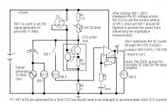
I don't understand the statement on udok's schematic "Vout/Ic(Q1)=80dB" the division of a voltage by a current is surely an impedance!
The ac voltage across the 1K resistor must be I ccs(ac) × 1000, where the ac current is in uA and the ac voltage in mV, therefore I ccs(ac) = Vr9(ac)/1000, again with voltage in mV and current in uA. The impedance of the CCS must be 1 / I ccs(ac), in Mohms if the ac current is in uA, 1 represents the "stimulus" voltage from the ac source.
Last edited:
One big disadvantage of the 2 transistor CCS is the temperature dependance. it is really only useable for uncritical circuits.
it is ok to use an opamp instead of the simple transistor amp.. but you can increase the gain up to 20 by changing R8 to 19-22k and still get 5 MHz bandwith with standard BC857.
if you want to measure the impedance at higher f this may be a factor.
The 80 dB is the factor between OUT voltage and CCS current.
Anyway i am very interested to see if the circuit works in practice too and which transistor is best suited for a current source. Simulation is one thing, measurement another..
Greetings,
Udo
Putting all the ideas together I have derived the following scheme, featuring a x100 / 40dB amplifier ( I don't need 5 MHz bandwidth ), hopefully this will work. If possible I will try it out tomorrow and post my results thereafter.
See attachment.
See attachment.
Attachments
Have you the time to explain what this is?
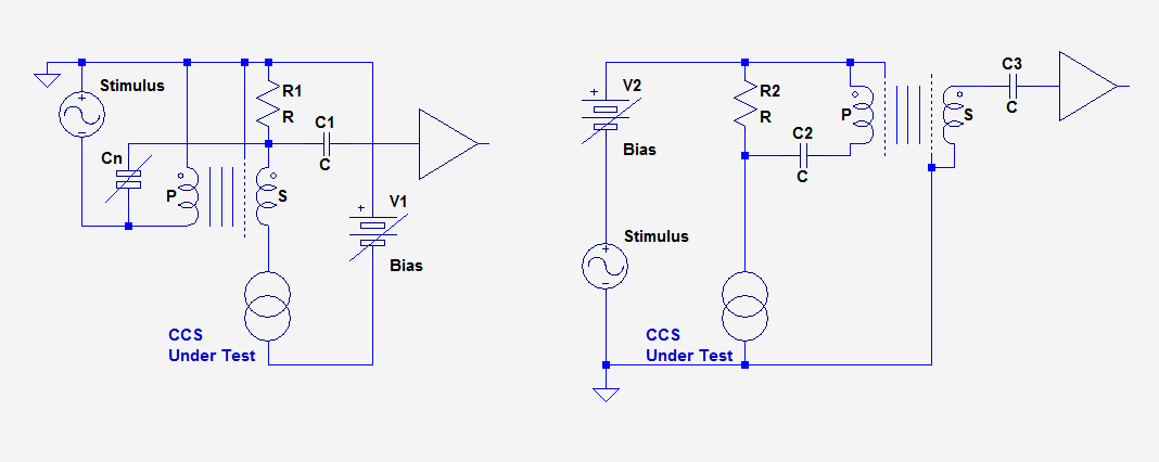
Here are the two setups outlined; in the first, the transformer is used as a floating stimulus injector.This sounds expensive, I am hoping to come up with something I can build from parts that I already have. However, like Andrew I'd be interested in learning more about this, if you have the time to teach us.
The transformer should preferably be equipped with a secondary screen, and the final residual can be perfected with a small neutralization cap.
This configuration has the drawback of letting the CCS current pass through the transformer.
For a few mA, even prerhaps up to some tens of mA, this shouldn't be a problem, but for higher currents the transformer needs to be gapped.
The second configuration dodges this issue, but it requires a primary and secondary screens.
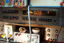
I made a quick test with the first transformer I could find: a Pikatron, apparently ~1:1.
I used the first configuration, except there is no screen.
The first pic shows the setup being crudely adjusted (without DUT). Next is the result: 8µV AC. Note that this residual is probably not mainly the 1KHz stimulus, but 50Hz hum: the setup is shielded, but very moderately.
Third pic is the DUT being measured:in this case a 100 Meg resistor (I didn't bother to use a real CCS with DC bias as for this type of evaluation, it isn't necessary).
The output voltage is now 385µV.
With ~5V stimulus, a shunt of 10K, this falls about right for 100Meg.
There is a ~20% discrepancy, but for a quick and dirty experiment, it is not particularly surprising.
Anyway, this shows that the method has a large potential: with 1000Meg, it would still be usable.
In addition, it is compatible with any type of CCS, including OpAmps, it is polarity-agnostic, and it allows the test in the real conditions: even with a 2W CCS, the way it is driven does have importance, because of the capacitance to the ambient space.
When you place the drive and the shunt at convenient places for an easy measurement, you lose these aspects, and they may be important because for a good CCS, the impedance will be dictated by capacitance for most of the frequency range.
Attachments


Last edited:
A high-compliance, 2W CCS functioning down to 1V is a tall order, but you can probably pick some ideas here:Yeah.
This 2 transistor CCS has two big advantages :
- it has a decent output impedance even with very low voltage headroom, and even at relatively "high" currents.
- it is super simple
HOWEVER it is a 3 terminal device... a bias current is needed for that second transistor. It is provided by R4 in my schematic. If the current through this resistor varies (for example, due to power supply ripple), then the two transistor CCS behaves a bit like a current mirror. So its PSRR is not that good. Replacing the resistor with a CCS fixes this.
So you need a CCS to bias this CCS, but it is a kind of teamwork : a simple JFET works well as a CCS only with high enough voltage drop and low current. So you can use a JFET to bias it, and you get a CCS that works well at low voltage drop.
If you can waste more volts on the CCS headroom, then other solutions can be more attractive (for example, a simple JFET, or a cascode, or a plain old BJT with more dropped volts on the emitter resistor, etc, there are so many possibilities).
But if you want a CCS that still works pretty well with 1V or less across it, it's going to need some feedback... it's possible to do better with an opamp, but that's way more complicated.
I'm looking for a CCS that works well with a total voltage drop down to about 1 V or less, for a current in the 5-10mA range, and with high PSRR... so far I like this combination. Does anyone know a better circuit ?
http://www.diyaudio.com/forums/solid-state/197104-improved-2w-current-sources-ii.html
This circuit was posted by Elvee:
Thank you Elvee, you have convinced me that this idea has potential. Is it possible to get a suitable transformer at a moderate price, say £10 GBP (~$15USD), perhaps used?
I don't have a particular need for my CCS to go down to 1v or less such as peufeu would like. I am going to go with the setup that I proposed in my last post. In the first instance I will use the exact same CCS as tested by my first method, that is the one with a 39k bias resistor such that I can make comparison between the 2 methods. After which I intend to replace the 39K resistor with a jfet CCS, to compare with the resistor method, perhaps I should also try making psrr measurements of the 2 types of CCS, as suggested by peufeu.
Elvee are you an electronics engineer, as your knowledge is pretty in depth for a hobbyist?
Also I like the retro digital meter, did you get this used or have you owned it for years?
A high-compliance, 2W CCS functioning down to 1V is a tall order, but you can probably pick some ideas here:
http://www.diyaudio.com/forums/solid-state/197104-improved-2w-current-sources-ii.html
This thread looks very interesting, I will need to give it a thorough read, and then I will probably have more questions! For now I only have one, that is, in the first post your third circuit uses LEDs, but why opto-coupler LEDs?
___________________
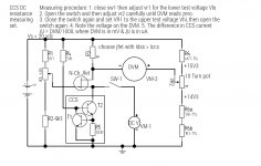
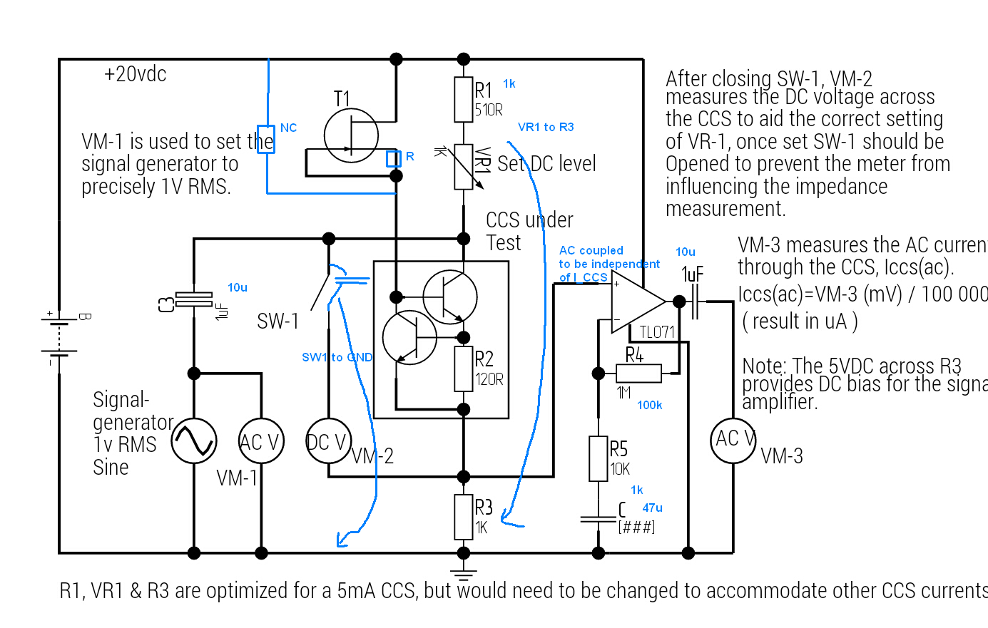
I have revised my scheme for measuring the DC resistance of CCS. On reflection the previous setup, given in post #97, using the ina131 wouldn't really work so well and also I think it was unnecessarily complex. The set up attached uses only 1 active device, a jfet, there is an explanation of the measuring procedure above the schematic.
The circuit uses a sensitive DVM ( 200mV fsd ) across a DC bridge, the purpose of the bridge is to null the large DC voltage across R3 due to the CCS and to leave only the tiny ∆V corresponding to ∆Iccs, the difference in current due to the internal resistance when the DC test voltage is varied. Therefore Rccs = ∆V / ∆Iccs.
Attachments
Yes, that is probably possible: ideally, the transformer should have at least one screen, but as I have shown, even a screen-less type can be made to work reasonably well by adjusting the neutralization cap.Thank you Elvee, you have convinced me that this idea has potential. Is it possible to get a suitable transformer at a moderate price, say £10 GBP (~$15USD), perhaps used?
You can find basic audio line transformers for a few £ or €, they would probably be usable. Even a mains transformer could be usable, within certain limits
Electronics is my bread and butter, and also one of my hobbies (not the only one, fortunately!)Elvee are you an electronics engineer, as your knowledge is pretty in depth for a hobbyist?
Just like many of my lab's components, this was an instrument that was scrapped by one of our labs, because it was thought to be beyond repair.Also I like the retro digital meter, did you get this used or have you owned it for years?
I salvaged it, and with lots of care, time and patience I managed to save it
Optocouplers LEDs work in infrared, with a lower bandgap and Vf than visible ones.This thread looks very interesting, I will need to give it a thorough read, and then I will probably have more questions! For now I only have one, that is, in the first post your third circuit uses LEDs, but why opto-coupler LEDs?
This means that operation is possible a few hundreds mV below visible ones, and since there is only one junction present, there is a first order temperature compensation with the transistor's Vbe (unlike two Si diodes which overcompensate)
Yes, that is probably possible: ideally, the transformer should have at least one screen, but as I have shown, even a screen-less type can be made to work reasonably well by adjusting the neutralization cap.
You can find basic audio line transformers for a few £ or €, they would probably be usable. Even a mains transformer could be usable, within certain limits.
I have numerous mains transformers, though I also have some audio transformers, small ones lt44 & lt700 they featured in a lot of early non HiFi transistors amplifiers, like in domestic radios, etc. I also have a bigger audio transformer, one of those 100 volt line to low z speaker matching transformers. I don't think any of them have a screen though.
Electronics is my bread and butter, and also one of my hobbies (not the only one, fortunately!)
I'm going to go way off topic here, but it is my thread and I'm going to allow it!
I wanted to be an electronics engineer from when I was quite young, playing with wires and stuff at age 3, my Father was a telephone engineer and he often brought goodies home from work.
I went to University straight after high school, which I realize now was a mistake as I was tired of academic stuff. I completed 2 years of an electrical & electronic engineering degree, with the exception of the maths part, I couldn't get my head round it and lacked the determination to put in the extra study necessary. I dropped out in 1993 and worked a dead end job for a few years, during this time I was an electronic musician and bass player and built a few musical projects, like filters and other stuff, biggest thing I designed and built was a vocoder, its a device that modulates the sound of an instrument, usually a synthesizer, with the human voice. To this end both the voice part and the synth part are separated into 10 frequency bands, 20 bandpass filters in total. The average level from each of the bpf's on the voice side are used to control voltage controlled amplifiers connected to the outputs of the bpf's on the synthesizer side. The effect is to impose a dynamic vocal frequency spectrum onto the signal from the synthesizer. They were really popular in the late 1970's.
That was just before i moved here to Stirling and undertook a course in psychiatric nursing at the University of Stirling, during that time I had neither the time or the cash to perdue my electronics hobby. When I finished my course in 2001, about a week before 9/11 in fact, I got back into my hobby with stuff left at my mums home. I started a permanent job as a psychiatric nurse. Soon after this I established a new work station in my new apartment and undertook a fairly intense period of electronics lobbying. I designed a number of circuits for generating percussion sounds, my intention was to build an analog drum machine. I met my wife at the beginning of July 2002 and the electronics hobby took a back seat.
Up until June 2nd 2008 things went on that way, we were married and had one daughter. I did do some electronics during this time, but not often.
On June 2nd 2008 I suffered a serious brain stem stroke and spent 3 months in hospital, by the following summer it was decided that my disabilities resulting from the stroke were too severe for me to continue working, I was pensioned off ( public sector job with good pension scheme ) At the end of 2009-beginning of 2010 I established a workshop in the same bedroom, new 'scope, decent bench PS, Signal Generator, 4&1/2 digit Bench dmm and a frequency counter that turned out to be faulty, I got a refund from the eBay seller. Throughout the time up until now I've been experimenting with various circuits using the many components I had bought.
I started working on a simple class A amplifier last autumn and that's what ultimately led me here. My interest in the impedance of CCS was that I was intending to use them as active loads for CE and CC amplifiers. The topic of measurement has become intriguing in itself.
Right now we've come full circle!
Well, life isn't a bed of roses generally, which is kind of fortunate as it could become boring.I'm going to go way off topic here, but it is my thread and I'm going to allow it!
../..
If you can survive its twists and turns, and still find energy to enjoy them, good for you....
Having some kind of passion or keen interest for something does certainly help
I looked at your circuit and might try it to compare with my results, presumably a small signal MOSFET would be better ( lower capacitances ) in a practical circuit?
Get a baseline with a standard value -- then you can then "normalize" the result.
You can also use a high quality line transformer -- like a Jensen JT123-FPCH -- or a line trafo you find on EBay. Audio Precision has an application note demonstrating the technique in measuring PSRR. With a trafo you also have to "normalize" but the Jensen I use is good from 10Hz to 200kHz. The Jensen I use is a bit more expensive but will take a hundred mA before it distorts.
You can make a crude amplifier with an LM317 -- modulating the ADJ pin -- this will work to about 1MHz. It comports OK with the device shown in Walt's "Current Sources 101", figure 5B
Attachments
Get a baseline with a standard value -- then you can then "normalize" the result.
You can also use a high quality line transformer -- like a Jensen JT123-FPCH -- or a line trafo you find on EBay. Audio Precision has an application note demonstrating the technique in measuring PSRR. With a trafo you also have to "normalize" but the Jensen I use is good from 10Hz to 200kHz. The Jensen I use is a bit more expensive but will take a hundred mA before it distorts.
You can make a crude amplifier with an LM317 -- modulating the ADJ pin -- this will work to about 1MHz. It comports OK with the device shown in Walt's "Current Sources 101", figure 5B
I've come across the lm317 based class a amplifier before, presumably using the 5 or 10 amp version you could get a bit of useful power out of it, though I'm sure the quality sucks goat cheese.
I do have a line transformer, though I'm not sure of the specs now, it is moderately sized so I suspect you could get away with passing 5-10mA DC through it. Haven't got around to trying the latest setup yet, had a pretty lazy day today, aside for taking the wee one to the park for awhile.
Gordon.
Putting all the ideas together I have derived the following scheme, featuring a x100 / 40dB amplifier ( I don't need 5 MHz bandwidth ), hopefully this will work. If possible I will try it out tomorrow and post my results thereafter.
See attachment.
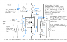
I have done some comments on your circuit. I am looking forward to see some
transistor measurements 🙂
Attachments
I have done some comments on your circuit. I am looking forward to see some
transistor measurements 🙂
I understand most of the suggestions, though I need clarification on a couple of points. The resistor in parallel with the jfet current source, does this mean, use both or instead of?
The DC voltmeter, you say the switch should be on the ground side, but is the meter to measure V across R3 or the voltage at the + side of the CCS?
Thanks again Udok. I too am looking forward to some more results. I think Jeanette might be taking the kids out tommorow ( they're on easter break just now )so I'll get peace to do some work!
Gordon.
The resistor in parallel to the current source is an alternative.
The CCS impedance depends on the impedance of the JFET CCS.
Use the resistor between Gate and Source to adjust the current of the JFET.
VR1 does not make mutch sense here, use it at R3 (to adjust the DC level) or at R2 (to adjust the current).
The DC voltage at the CCS is (VCC - I_CCS*R1), no need for VM-2 at that position. Use
VM-2 to measure voltage across R3 (I_CCS = V_R3 / R3)
Greetings,
Udo
The CCS impedance depends on the impedance of the JFET CCS.
What is the relationship? Is it linear, as in Zccs = K Zjfet, where K is a constant.
Use the resistor between Gate and Source to adjust the current of the JFET.
Greetings,
Udo
I know that you can do this. If you don't mind could you explain how it works, I think its something to do with negative feedback but I don't exactly know how it works? and what is the relationship between the jfet ccs current and the value of the resistor?
Cheers,
Gordon.
The relation between jfet current and R between G and S is nonlinear...
Look at a diagram for I over V_GS and draw a line I = V_GS/R into the diagram. The crossing point define I.
Assume that Ic1 through T1 of the CCS is increased by dIc1.
The dIc1 causes a dU = dIc1 * R2. T2 sees this dU at its base and adjust its
collector current dIc2 by dU / rm (rm = 1/gm = 26mV / Ic2)
The collector of T2 sees the load Rc2 = R_jfet || R_BE1.
The voltage at collector of T2 goes negative by dIc2 * Rc2.
This in turn decreases T1 collector current...
R_BE1 is about rm ( 1 + Beta) or about 5k at 1 mA.
It is enought that the R_jfet >> R_BE1 for good DC performance.
Greetings,
Udo
- Status
- Not open for further replies.
- Home
- Amplifiers
- Solid State
- How do you calculate impedance of a current source?