Further, the brain re-creates the fundamental tone from the overtones and you "hear" it (or in more precise language that is less ambiguous than re-using the word "hear", you "perceive" it). I know that's a concept that doesn't feel right to persons of an engineering disposition but it is true anyway.
I don't differentiate. To me, when I sense something with my ears, I call that hearing.
If we want to relabel the hearing of anything below 20 cycles to "perception" in order to satisfy a facile hearing weight curve, that's up to you.
Edit: The thing I don't understand is, in a thread where someone is looking to reproduce 16 hz, why did we start with advice about how to do it, and then suddenly switch to a disagreement about FM curves vs hearing, devolving into "nobody can actually hear that" on page 8?
Last edited:
Without knowing anything about the space (the interior of the church) or the current spl level at 16 hz (he has to stand right in front of it in a quiet empty church and put his hand on it to even perceive 16 hz) how do you know how many more speakers are required? I think it's going to be a lot more than 3.
I don't need to based on his observations of his existing 'sub' system, just that to get the same performance an octave below it requires a total of 4x the acoustic power to achieve it, though in retrospect I see I could have explained it better; i.e., if his current sub system is ~flat to 115 dB/m/32 Hz with a 32 Hz Fs 15"/10 mm Xmax and dual 18" PRs, then as you 'think' 😉, he'll need the equivalent of [4] 16 Hz Fs 15"/10 mm Xmax and [8] 18" PRs in however much total net Vb is required to do it ~flat to 16 Hz, a significant increase in cost/bulk regardless of how he decides to do it.
Since pipe organ design doesn't follow human hearing efficiency requirements, there's no need for a sub system to do it.
GM
Hi Bach On,
Post #75: "... I'm a bit hung-up on the port, let me request the details..."
While you are addressing this at JAG, I'll try to answer:
As your enclosure is deep enough (24" dimension) you only need a straight 17" to 18" long piece of PVC pipe w/ a 6" I.D.
You could even use two 4"I.D. ports @ 14"long ea. (Port area of both ports together=162.10cm^2.). The port velocity will go up a bit.
Or, you could add a shelf port under the enclosure reflecting the same cross-sectional area(s) and length(s).
Generally, the port can be added just about anywhere, but it should have enough room on both ends so that it is not blocked, and so that the port is not extended by, e.g.: the inside enclosure walls. I like to see at least 3/4" rounding of both ends of the pipe, that means, that on the inside a small board should be added (e.g.: 8"Dia.) to allow for the round-over.
Because of the height of the box it may be a good idea to simulate it in Hornresp as a MLTL (mass-loaded transmission line) just to see if there is an optimum point for the port. Don't have time for that right now.
Regards,
Link for ports: http://www.subwoofer-builder.com/flare-testing.htm
Last edited:
Yes . . . so put it outside the (existing) box. We’re not talking about an art object or something that has to hide unobtrusively in your living room. This is a machine intended to efficiently convert electrical energy into acoustic energy that will be hidden in an organ pipe loft.Generally, the port can be added just about anywhere
Helmholtz Resonators - Basic Analytic Devices
note the external port tube in the diagrams . . .
Just a guy, First, relax. This isn't personal.🙂
It is to me. When I provide graphs and scientific evidence and other people offer opinions that are going to cost a LOT of money and not better your situation at all I take it personally. If they have no proof of their own to offer to back up their opinions it shows they either did not read or did not understand what I posted. I have no patience for that.
I get it. A port offers 12 db gain for almost no cost. We just don't quite agree on the ease or complexity of adding a port. That's probably just MY HANG-UP.
...
Since I'm a bit hung-up on the port, let me request the details. 😕 I'm assuming a 90 degree elbow goes in the 6" hole I'll need to cut in the cabinet. It will be solidly glued in place and sealed. Then a length of straight ABS pipe will be inserted into the elbow on the inside of the cabinet. More glue (pipe adhesive) will hold it in place - that's why you say no support will be needed.
tb46 suggested 17 3/4 inches for the port. You suggested a different length. I assume the elbow has to be included in determining that length.
You even hinted that there MIGHT be some advantage to a different sized port.
The port I showed in my sim is a bit bigger and longer than the one TB46 showed I think, so mine will have less air velocity for a given spl, and less chance of port noise. If this were my project I'd go for an even longer and larger port to reduce velocity further.
At 60.5 cm port length you don't need any elbows. It will easily fit on any side of your box. Your smallest box dimension is larger than 60.5 cm so it could be placed ANYWHERE on the box without elbows.
EDIT - oops, I did the conversion and this is not accurate. It is too long to fit across the narrow sides of the box without elbows. I'll work that into my final sim and there won't be elbows, I'll either reduce port length or stick it on one of the ends. Sorry for this confusion.
I've mentioned this before, I'll mention it again. It's super easy to add a port to a box.
I have one of these, a 3 inch hole saw.

I cut a 3 inch hole in the box, it takes about 5 minutes. You have to stop every few seconds to blow out the sawdust or it just spins the sawdust around and doesn't cut effectively.
Then a length of 3 inch abs pipe is required.
An externally hosted image should be here but it was not working when we last tested it.
You can find this everywhere for free. A length this short is considered scrap, a dumpster behind a plumber will probably be full of it.
This 3 inch abs pipe should fit TIGHT in a 3 inch hole cut by a hole saw. So tight you have to hammer it into the hole. It fits SO TIGHT there is no glue required to hold it in place, in fact if you try to manually remove it without tools it's not easy to do.
You can even test this, if you have a 3 inch hole saw, cut a hole and see if 3 inch abs fits tight. I can't guarantee that all 3 inch hole saws cut EXACTLY the same diameter hole, but all the ones I've tried make a VERY tight hole for 3 inch abs.
Then add 3 more 3 inch holes and 3 more 3 inch abs pipes. 4 3 inch pipes have the same cross sectional area as 1 6 inch pipe, so they are effectively the same thing.
OR do this with a 6 inch hole saw and a 6 inch pipe BUT a 6 inch hole saw is a lot harder to find and may or may not be a tight fit for a 6 inch abs pipe.
OR make the port out of wood scraps in a square cross sectional area shape, cut a 6 inch square hole in the box and glue the port in. But no elbows are required.
Seriously if you use a 3 inch hole saw the whole job will take about 15 minutes tops, no elbows, no glue, just drill four 3 inch holes, stuff four 3 inch abs pipes into those holes and it's done.
If you don't own a 3 inch hole saw I wouldn't buy one, I'd build the port from scraps of wood and glue it in the box, but seriously if you can build a box you can retrofit a port just as easily. This isn't difficult stuff. And it would be hard to believe that no one in the whole church including THEIR family and friends doesn't have a 3 inch hole saw you can borrow for 15 minutes.
NEXT -
I will look at your pics, find out where the driver is located and incorporate the physical details of port and driver location into the simulation. These details all matter. I'll do that when I have a few free minutes.
Last edited:
Yes . . . so put it outside the (existing) box. We’re not talking about an art object or something that has to hide unobtrusively in your living room. This is a machine intended to efficiently convert electrical energy into acoustic energy that will be hidden in an organ pipe loft.
Helmholtz Resonators - Basic Analytic Devices
note the external port tube in the diagrams . . .
You could... but it's easy enough to put it inside the box. External ports are ugly and get int the way.
I don't need to based on his observations of his existing 'sub' system, just that to get the same performance an octave below it requires a total of 4x the acoustic power to achieve it ...
Maybe if we assume the acoustic properties of his space are equal at all frequencies this might be true, but this is not usually the case. It's entirely possible that his space offers a lot of support at 32 hz and is a complete sieve at 16 hz. These are things we can not know and I'd personally rather not speculate.
If I'm going to make a recommendation it will be on how the sub will perform outside because I can basically guarantee that. I can't even guess at how it's going to perform at a random location in a building I know absolutely nothing about.
... as you 'think' 😉 ...
Yeah, # of PRs required was just a guess. I've never simulated a PR system. I find that a free slug of air in a port is a MUCH better solution than costly passive radiators every single time. I'd never consider them personally and would never recommend them unless the #1 system goal was small size.
Resonances are never a problem. Enclosure shape, driver and port location on/in the box and a bit of stuffing can always work to your advantage to make sure you have smooth response. No need to be scared of resonances as half the people in this thread seem to be.
I looked at your thread and can't see any of the pics. When I click the pic links it wants me to log in.
I don't register to forums just to view pics. You can either post the pics here or just tell me where the driver is located on the box. Otherwise I can't optimize the sim for best port location.
Posting the pics here is probably best, then we can advise on bracing and other things too. You mention in the thread that there are pics of the internals, ribs and other stuff going on too.
I have absolutely no problem hearing this.
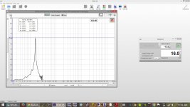
What is that a spectrum of? The signal to the amp, or from a mic (placed where)???
Organ loft . . . full of pipes . . . usually "hidden" except for the front row (and I've seen cases where those were silent, there for "show only").External ports are ugly and get int the way.
It's not about "looks", it's about "works" . . . there's no point in compromising that to fit the port pipe into the box . . .
What is that a spectrum of? The signal to the amp, or from a mic (placed where)???
Laptop driving receiver through hdmi, OmniMic V2 @ mlp facing up.
SPL isn't calibrated properly, but it's close.
Organ loft . . . full of pipes . . . usually "hidden" except for the front row (and I've seen cases where those were silent, there for "show only").
It's not about "looks", it's about "works" . . . there's no point in compromising that to fit the port pipe into the box . . .
If it were a choice between form and function I agree, function every time. (Or completely change form so it's also fully functional.) There's no compromise here though, it's no harder to stick it inside than outside. Box volume is large enough that it doesn't matter either way.
OP is free to decide inside or outside but I don't see it being any harder to tuck it inside and no one is going to trip over it.
Organ loft . . . full of pipes . . . usually "hidden" except for the front row (and I've seen cases where those were silent, there for "show only").
It's not about "looks", it's about "works" . . . there's no point in compromising that to fit the port pipe into the box . . .
Maybe a stand for the sub could be fashioned using 3 or 4 PVC pipes, one of which is open on one end for the port?
Maybe if we assume the acoustic properties of his space are equal at all frequencies this might be true, but this is not usually the case. It's entirely possible that his space offers a lot of support at 32 hz and is a complete sieve at 16 hz.
I find that a free slug of air in a port is a MUCH better solution than costly passive radiators every single time.
Resonances are never a problem.
Again, what I provided is the same requirement for adding an octave lower pipe to an existing organ, so lacking any info in the various pipe organ design tutorials I’ve read over the decades even suggesting considering the room’s acoustics, I figure I’m on pretty solid ground. If nothing else, it’s a good starting point and if the church is a sieve down low, then adding more acoustic power won’t help and maybe even need attenuating to keep it within noise abatement regulations.
Don’t know what alternate reality you live in, but around here there’s a point where port resonances become high enough in amplitude to be a major problem, comb filtering with the driver’s response and once damped, its efficiency is so low that it becomes a ~I.B. low Q response with only a little bit of gain down around/at Fb, i.e. it’s basically a well damped TL. Fine for high SQ, but not what we want for reproducing an acoustically ~35 ft long resonant air slug organ pipe at high SPL AFAIK.
GM
Hi DrDyna,
Post #94: "Maybe a stand for the sub could be fashioned using 3 or 4 PVC pipes, one of which is open on one end for the port?"
4ea. 3"I.D. pipes provide the same area as 1ea. 6"I.D. pipe. Maybe 4 legs w/ 90°s at the bottom would be nice. 🙂
Also (for JAG), a 3"nom. pipe has a nominal O.D. of 3.500", no wonder it's a tight fit.
Regards,
Last edited:
Again, what I provided is the same requirement for adding an octave lower pipe to an existing organ ...
No you specifically said "In short then, you'll need three more speakers just like it except designed around a ~14-16 Hz Fs driver/tuning or equivalent 1/4 WL tuned [closed] pipe system.
That's a firm recommendation for the amount of speakers he needs to accomplish his goal. And that's exactly why I asked how you know how many speakers he needs if you don't know anything about the building, how the current sub measures in the building or anything at all about the building acoustics.
That may not have been your intent but that's how it reads. My follow up question should have made this pretty clear too.
Don’t know what alternate reality you live in, but around here there’s a point where port resonances become high enough in amplitude to be a major problem, comb filtering with the driver’s response and once damped, its efficiency is so low that it becomes a ~I.B. low Q response with only a little bit of gain down around/at Fb, i.e. it’s basically a well damped TL. Fine for high SQ, but not what we want for reproducing an acoustically ~35 ft long resonant air slug organ pipe at high SPL AFAIK.
GM
I'm sure port resonances can be a problem in a badly designed sub but what you are describing is NOT a reflection of the sims I showed. Please point out which sim I showed where port resonances are high enough to be a major problem.
Failing that, if you were just commenting on my comment "Resonances are never a problem", let's revise that to "Resonances are never a problem in good designs" for the people that don't understand that EVERYTHING can be a problem in a bad design and need that little point clarified.
Not sure if that clears it up sufficiently or not, but if not my reality is pretty nice, a balmy 58 degrees today, stop by sometime.
Last edited:
Maybe 4 legs w/ 90°s at the bottom would be nice. 🙂
The box is probably 100 lbs, maybe 200, probably way to much for an elbowed abs pipe to support. If they are wood legs that's a different story, but it would be an odd looking little duck. I prefer internal ports, but it really doesn't matter much, the box is big enough either way.
Also (for JAG), a 3"nom. pipe has a nominal O.D. of 3.500", no wonder it's a tight fit.
Regards,
Huh, what do you know. I just learned 2 new things. Abs 3 inch pipe is 3.5 inches externally and my hole saw (and all the other hole saws I've ever used for this purpose) were 3.5 inch hole saws. Thanks for that. I guess I've never actually seen a 3 inch hole saw, the 3 or 4 I've used were apparently all 3.5. Not sure why I didn't know this, I guess I just had no reason to measure and just assumed the pipe and the saw were 3 inches.
My hole saw has no markings, I just assumed it was 3 inch for some reason. I just measured it with my calipers and it measures 3.48.
Don't try to hammer a 3 inch abs pipe into a 3 inch hole. It isn't going to work. Sorry for the confusion. Get a 3.5 inch hole saw if you want to do this, and make sure it fits tight (like mine does, and the others I've used) on a piece of scrap before drilling holes in the box. If it's not a tight fit glue isn't going to help.
Last edited:
If it's not a tight fit glue isn't going to help.
I fixed one I f---ed up once using the wrong hole saw by wrapping a few turns of duct tape around the pvc 😛
Hi Bach On,
In reference to Post #83: "... simulate it in Hornresp as a MLTL...".
I did that, and transferred the data to AkAbak, there I moved the port location up and down. Looks from your pictures that your driver is about 1/3 down from the top, if you put the center of the port (ports) about another 1/3 down (or a third from the bottom) , and you will be fine.
Don't let all the different port dimensions confuse you. For a given tuning frequency, if you make the diameter smaller the port gets shorter, make the diameter larger, and the port must get longer. My final recommendaton for a single port of 6"I.D. should be 17-5/8" long. Use the same length for each individual pipe if you go w/ 4ea. 3"I.D. ports.
Just one more note, by putting a single driver into a very large enclosure tuned to a very low frequency you create a system that will not take a lot of input power before it reaches its excursion limit. At the upper excursion peak past the tuning point (~23Hz) it takes only 11W to reach Xmax. Below box tuning you will need a low cut (high pass) filter that reduces the power going to the box below ~15Hz. In Post #72 18Hurts states that the "Crown XLS1500 has a high pass LR filter at 20Hz", you need to keep that in mind too.
Regards,
- Status
- Not open for further replies.
- Home
- Loudspeakers
- Subwoofers
- 16Hz for church organ