George, the ouput impedance of my SS dac is a high 2.6kohms. You said it may not be a problem in terms of bass or highs roll off. The sound is fantastic and I cannot detect any sort of rolloff or sound degradation. All the posts I have read seem to indicate this is not a good match for the LSA. Just curious as to why it is working so well?
I do not know the input impedance of the LSA. It would seem it must be over 25Kohms for this combo to work so well?
I do not know the input impedance of the LSA. It would seem it must be over 25Kohms for this combo to work so well?
optocouplers are expensive and hard to match, I haven't find any that tracked well. Maybe George found some that do track well.
Look at my very first post (No. 5) of this thread on how to match them yourself.
http://www.diyaudio.com/forums/anal...attenuator-new-passive-preamp.html#post924390
Administrators have allowed a rehash of the first post, so all can easily find and do one for themselves.
Cheers George
Last edited:
George, the ouput impedance of my SS dac is a high 2.6kohms. You said it may not be a problem in terms of bass or highs roll off. The sound is fantastic and I cannot detect any sort of rolloff or sound degradation. All the posts I have read seem to indicate this is not a good match for the LSA. Just curious as to why it is working so well?
I do not know the input impedance of the LSA. It would seem it must be over 25Kohms for this combo to work so well?
The Lightspeed Attenuator mimics a 10kohm logarithmic series/shunt pot, so your dac should have no problem, it would be nice if it were 1kohm or lower, 2.6kohm is stupid high for an output impedance.
The 2.6kohm with the capacitance of the interconnect will determine the HF roll off.
If the interconnect is high capacitance, say 300pf per foot and you use 2mts of it, this will be approx. 1800pf of capacitance. Which will equate to with your 2.6kohm output impedance, a HF roll off of -3db at around 34khz, a bit low. That's why I always say use quality interconnects that have low capacitance <100pf per foot.
Cheers George
Thanks George. My IC's are very low capacitance so all is indeed good. Not sure why the output impedance is so high on my dac, but it is wonderul sounding!
wow the led tester is pretty cool, sorry I am slow didn't made the link!
I wonder how good you can match them and how many you need to buy. Just to say when I match stereo volume controls the rejection rate is 50% and all needs some sort of adjust with a ladder input.
I wonder how good you can match them and how many you need to buy. Just to say when I match stereo volume controls the rejection rate is 50% and all needs some sort of adjust with a ladder input.
wow the led tester is pretty cool, sorry I am slow didn't made the link!
I wonder how good you can match them and how many you need to buy. Just to say when I match stereo volume controls the rejection rate is 50% and all needs some sort of adjust with a ladder input.
If you purchase 15 pieces of NSL32SR2S, you should be able to get 2 sets of matched quads to make 2 x Lightspeed Attenuators. You could get real lucky and get 3 x matched quads.
Cheers George
Are you able to match diodes in each channel so the max deviation is 0.5 db ?
I found the explanation on your website most interesting, I discarded the idea of this type of attenuator because of the difficulty to match the parts but this is interesting. I noticed too that high pressure volume pots sounded very good to even better than rotary switching.
I found the explanation on your website most interesting, I discarded the idea of this type of attenuator because of the difficulty to match the parts but this is interesting. I noticed too that high pressure volume pots sounded very good to even better than rotary switching.
Are you able to match diodes in each channel so the max deviation is 0.5 db ?
I found the explanation on your website most interesting, I discarded the idea of this type of attenuator because of the difficulty to match the parts but this is interesting. I noticed too that high pressure volume pots sounded very good to even better than rotary switching.
Yes you can. And if your not up to it you can always build the dual mono which you can afford to be a little lax on, I posted a circuit for a few posts back.
As for high pressure wipers on rotary pots, I'd like to know which ones are, as I've seen inside so far what I consider to be the best the Alps Blue Velvet and Black Beauty and they are as light as a feather contact with their wiper on the resistive track as not to wear the resistive track out.
And not only is this light pressure a source of sound problems it's the two dissimilar materials, wiper being metal and the resistive track being either carbon or conductive plastic.
Cheers George
The optocouplers are nice but nowhere ideal. This config is controlling them by voltage while their true control is current. Also we have the problem of no zero volume. But as far as I have heared I want to test it further. Never use them in balanced mode tho. They are far to unlinear and uneven.
Ok LSA lovers and George. I upgraded all the internal hook up wire to some nice solid core silver in cotton. I also upgraded the RCAs with some nice Bocchino I had. The results have been outstanding.
I still want to try directly hooking up the output of my dac to the input R and L channels of the LSA by placing it in my dac. I am still in need of some direction here.
I understand I have to simply connect the right and left channel signal wires of the dac and LSA . These were the center rca signal wires of both the dac and LSA. Since I no longer will have input RCA jacks what do I do with the dac's RCA ground wires that used to go to the RCA's? The RCA input jacks on the LSA were also all grounded together....now That I am not using the RCAs what do I do?
Lastly, I assume I still ground the LSA to the chassis from the ground wire on the rear of the board.
I may be making this harder than it is, but I am learning and really want to do this little project. Love the idea of bypassing a set of ICs and two sets of RCA jacks.
Ok LSA lovers and George. I upgraded all the internal hook up wire to some nice solid core silver in cotton. I also upgraded the RCAs with some nice Bocchino I had. The results have been outstanding.
I still want to try directly hooking up the output of my dac to the input R and L channels of the LSA by placing it in my dac. I am still in need of some direction here.
I understand I have to simply connect the right and left channel signal wires of the dac and LSA . These were the center rca signal wires of both the dac and LSA. Since I no longer will have input RCA jacks what do I do with the dac's RCA ground wires that used to go to the RCA's? The RCA input jacks on the LSA were also all grounded together....now That I am not using the RCAs what do I do?
Lastly, I assume I still ground the LSA to the chassis from the ground wire on the rear of the board.
I may be making this harder than it is, but I am learning and really want to do this little project. Love the idea of bypassing a set of ICs and two sets of RCA jacks.
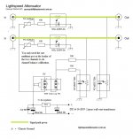
All input and output rca shields went also to chassis on the Lightspeed, so the same applies to the rca shield on the cdp/source and the rca shield of the amp.
As per the circuit, no power supply or wall wart of the Lightspeed get grounded they float.
Cheers George
Attachments
Completed putting the LSA in my Yamamoto YDA 1 dac. Now this great dac has the nice LSA Attenuator and I bypassed two sets of RCA jacks and a set of ICs.
Sounds even more transparent and simplified my set up nicely.
Sounds even more transparent and simplified my set up nicely.
Nyone interested in a gb? I can set it up and match.
I've just bought a Coffee balanced kit, (probably shouldn't mention that here!!) for a KGST headphone amp which I'm about to build, so not tried it yet. OK, I know LDR's aren't supposed to be great for balanced, however, I'm intrigued by them and, if all goes well, I'd be interested in experimenting further.
So, yes, I'd be interested in a GB if we could get enough involved. I notice Digikey has good price breaks as you buy more. also, I suppose the more people involved, the more matched quads (octets!!) you'll get.
Shunt attenuators with ldrs are easy and sound great. No need to match. I never thought it would be that great but it is. Matched octets will not happen. I've matched 500 at a time on my jig and matched octets are not common even with supposedly great odds.
So I suggest shunt like attenuators when doing balanced with ldrs. Use ldrs as series resistors and a pot as the variable resistor between them.
So I suggest shunt like attenuators when doing balanced with ldrs. Use ldrs as series resistors and a pot as the variable resistor between them.
Or, for a differential balanced shunt attenuator, use a premo quality fixed resistor like TX2575 in the series position and a variable LDR shunt between the phases. I've used this approach for a 100K balanced volume control in a balanced Atma-Sphere MP-1 and it sounds great.
There are a lot of vishay foils for cheap on eBay right now from China and Hong Kong that I "assume " are genuine as they look like pulls rather than brand new. If you want the full effect of having ldrs in series and "shunt" then use Davids idea but put an ldr in series with the TX2575 but after the attenuator. Set it to a low value so it wont wander. Remember in balanced we need super close match between positive and negative lines.
If you're after perfect CMRR, you can't get near that with an LDR in the series position. Besides, why add the flavor of two resistors in series? Perfect CMRR is achievable only with a fixed series resistor-- particularly so with a TX2575 of .01% tolerance. Then with an LDR in just the shunt position between the differential phases, any tracking deviation between LDRs causes only a L/R channel imbalance that can be eliminated with a balance control. For a 50K or 100K volume control, a 500K or 1M control pot in place of the customary 10K pot used in a passive Lightspeed, drives the LDR shunt to a much wider operating range-- up to 30Kohm or more-- as appropriate for a 50K or 100K volume control in an active preamp. George earlier mentioned that this is similar to his Mk I version of Lightspeed, and that his MkII sounds better. But if the goal is a balanced control with perfect CMRR and an operating range above 10K, I think this approach is the only game in town, and it does sounds superb with a TX2575 series resistor. These can be purchased directly from Texas Components in any value up to 100K, for $10-$15.
You're absolutely correct David, about CMRR. However if you want the flavor of an ldr in series its still possible in your situation. Only because you stated using 100k. You drop the value of the ldr down to near its minimum. .01% is easy then as at 40ohm the ldr wont waiver.
- Home
- Source & Line
- Analog Line Level
- Lightspeed Attenuator a new passive preamp