I did a bit of an amateur summary a few years ago (2008!) on post 1524 & 5 - a bit out of date now but maybe still useful to someone ....
Hi Andrew, not sure what you've done, I looked at post 1 and it seems the same??
Cheers George
George,
Post #1 is yours, so only you can edit it. I believe what Andrew is suggesting is that you modify post #1 to begin building an index of the important posts in this thread, which has now grown to 537 pages.
George,
Post #1 is yours, so only you can edit it. I believe what Andrew is suggesting is that you modify post #1 to begin building an index of the important posts in this thread, which has now grown to 537 pages.
Thanks Mike, yes now I see what Andrew meant, I will get on to it soon an attach more circuits an such.
Cheers George
I am not allowed to do anything.Hi Andrew, not sure what you've done, I looked at post 1 and it seems the same??
Cheers George
Only the Thread originator has perpetual rights to edit the first post.
I am not allowed to do anything.
Only the Thread originator has perpetual rights to edit the first post.
I've emailed the admin, and asked if I can get permission to add circuits and such to the 1st post, they will get back to me.
Cheers George
All done.
Cheers George
Thanks George, that helps to avoid wading through many pages.
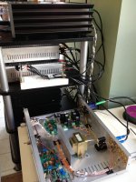
Spent some time earlier today adjusting the channels in the Lightspeed and used an A/B preamplifier switch to compare between it and a regular Alps pot pre. The Lightspeed was better in every area by a distance, quite impressive. Attack and decay were much better from the Lightspeed, so was bass, mids, treble.
Attachments
All done.
Cheers George
Thx for the Update ! Good job as it makes it much easier for newcomers.

George,
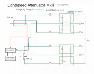
the symbol for signal ground in post1 pic1 (left) is a triangle.
In pic2, The symbol for signal ground and power ground are both the E style.
Can you keep the E style for the chassis connection and change the signal ground in pic 2 back to the triangle to match pic 1?
pic3 shows the three bars style traditionally used for power ground. Can this be changed back to signal ground triangle.
This would make all the diagram consistent and compatible.
Last edited:
the Buffer shown and the B1 Buffer can both easily drive a 33k Receiver impedance.4th: Is the buffer Nelson Pass designed a few years back for the Lightspeed Attenuator (later to be known as the B1 Buffer) to be able to drive low input impedance amps of less than 33kohm.
It's the interconnect cable that provides a potentially higher loading.
The B1 Buffer can drive 1nF||10k to line levels (~6Vpp from a CDP). The 10k draws only 0.3mApk whereas the 1nF can draw >1mApk depending on the HF content in the signal.
George,
the symbol for signal ground in post1 pic1 (left) is a triangle.
In pic2, The symbol for signal ground and power ground are both the E style.
Can you keep the E style for the chassis connection and change the signal ground in pic 2 back to the triangle to match pic 1?
pic3 shows the three bars style traditionally used for power ground. Can this be changed back to signal ground triangle.
This would make all the diagram consistent and compatible.
Thanks Andrew, chassis earth and the earth bought in by the interconnect from the power are one in the same thing on the Lightspeed, yes the symbol is wrong but you get my drift, what should not be there I just noticed is that the negative supply rail should not be earthed.
I will ask Mooley to submit/edit a corrected pic for it.
As for the buffer if you go back through the thread posts, Nelson did design it originally so the Lightspeed could better be used with low input impedance amps.
Cheers George
Thanks Karl (Mooley) for changing the 2nd pic again, that Andy is such a stickler for the correct protocol.
Cheers George
Cheers George
Thanks George, that helps to avoid wading through many pages.
Spent some time earlier today adjusting the channels in the Lightspeed and used an A/B preamplifier switch to compare between it and a regular Alps pot pre. The Lightspeed was better in every area by a distance, quite impressive. Attack and decay were much better from the Lightspeed, so was bass, mids, treble.
Thanks Whaleman, your comments are what's typical of the first time listeners, and we should get more of it, I know it's a diy forum but the end result is in the listening.
Cheers George
I have a question on how to wire the LSA into my current Yamamoto dac. I have an LSA that I would like to remove from the current chassis and place inside my dac. I would be able to avoid an IC and rca jacks for direct hook up from the Yamamoto output to the LSA.
Please let me know how to deal with the grounding going from the dac output (now grounded RCAs ) to the LSA input ( now grounded Rca's). Not exactly sure how to proceed. I like the idea of eliminating two sets of rca jacks and an interconnect. The LSA output will not be changed and I will continue to power it with a battery supply.
Thanks for any help.
One other question. My amp has an input impedance of 100k and the Yamamoto while it has 3.1volts of output has a rather high output impedance of 2.6kohms. I think. I have read that under 1 k is ideal? I am getting great sound, but do question the under 1k ohm comments ....?
forget about calling something "ground".
Think instead about using a two wire input connection and then about a two wire output connection.
The repeat for the other channel.
ALL circuits require a two wire connection.
Think instead about using a two wire input connection and then about a two wire output connection.
The repeat for the other channel.
ALL circuits require a two wire connection.
Last edited:
I have a question on how to wire the LSA into my current Yamamoto dac. I have an LSA that I would like to remove from the current chassis and place inside my dac. I would be able to avoid an IC and rca jacks for direct hook up from the Yamamoto output to the LSA.
Please let me know how to deal with the grounding going from the dac output (now grounded RCAs ) to the LSA input ( now grounded Rca's). Not exactly sure how to proceed. I like the idea of eliminating two sets of rca jacks and an interconnect. The LSA output will not be changed and I will continue to power it with a battery supply.
Thanks for any help.
Bill, your dac is tube and while there will be no problem with a stereo Lightspeed put inside it, there will be a problem keeping it calibrated (channel balance).
As the tube and heaters will cause big temp differences that will cause the Lightspeed to loose it's calibration, from the first 1/2hr to a few hours.
This temp inside a tube dac could be at ambient say 15c cold to over 40c hot after a few hours.
You could do it, but you'll need a dual mono Lightspeed with L & R volume controls. here is the circuit if you want to mod the stereo into a dual mono, and you would omit the 25 turn calibration pot inside, just bridge it out.
The 3.1v is no problem and the 2.6kohm output impedance should be fine just use interconnects that <100pf per foot.
Saying all that I think it would be more comfortable putting a dual mono inside the amp.
Cheers George
Attachments
Last edited:
Thanks George. The DAC is SS and stays very cool.. It is the YDA-1. I assume based on this the unipot version of the LSA is fine? No need for the dual mono?
Am I correct in assuming that one can not get the matched components for this circuit without matching them yourself?
optocouplers are expensive and hard to match, I haven't find any that tracked well. Maybe George found some that do track well.
- Home
- Source & Line
- Analog Line Level
- Lightspeed Attenuator a new passive preamp