Hello Sheldon,
Perhaps off subject, maybe not ! When I just modeled PSUD2 your supply, guessing at values, I got over 1.2 VAC of simulated ripple, and it rings - a whole lot!!! Ringing is a problem I think. I have no way to sim a solid state and tube rectifier in parallel, but the ringing shows up with either device rectifying, on a 15% current step at 7.1 seconds.
Jeff
The final cap is actually 8u. Remove that first current source. Make the final current source 50mA.
Sheldon
Ian,
I wasn't thinking in terms of ripple reduction, as much as "fast" PEAK INSTANTANEOUS current delivery to the Finals stage. Chokes over 20 Ohms preclude that in my experience and at my present understanding level. You recently HEARD this effect when you lowered the DCR on your Lundahls!!
MAYBE a LW will work with 800 mVAC on the B+ feeding the amp, maybe ??? The INPUT stage, in my experiences, needs LOW ripple, under 2 mVAC !! Comments ?
Jeff Medwin
Hi Jeff
The way I did it made sense to me at the time.
What you don't know is the serial resistance I added to the transformer primaries. 😉 no transformer ring. Incredibly fast response in PSU II...
In any case, please re-read sheldon's posts. You are still thinking in the world of input and output stages.
You need that low ripple in your amp, but in my amp you don't.... It cancels... So my amp even with 30 ohm DCR total will likely have faster response than yours and have lower noise floor.
Ian
Last edited:
Please also realize that there is a reasonable limit to this kind of noise cancellation too. Reducing the DCR on the lundals by running the coils in parallel seemed nice at first, but there was ripple that could not be cancelled out. So I have it back to 30 Ohms per channel now. I'm very very pleased with it.
True.Lots of things look good on paper.
Lot of things look good in simulations too.
But theory is no substitute for experimental evidence.
Member
Joined 2009
Paid Member
Ciro,
If you can indulge me in an off-topic question. I know you have a huge experience with OPT and tube amps in general. Did you ever feel that the sound you value can be achieved from an OTL amplifier, or even one with a SS power stage with tube front-end ?
If you can indulge me in an off-topic question. I know you have a huge experience with OPT and tube amps in general. Did you ever feel that the sound you value can be achieved from an OTL amplifier, or even one with a SS power stage with tube front-end ?
I wasn't thinking in terms of ripple reduction, as much as "fast" PEAK INSTANTANEOUS current delivery to the Finals stage. [...]
MAYBE a LW will work with 800 mVAC on the B+ feeding the amp, maybe ??? The INPUT stage, in my experiences, needs LOW ripple, under 2 mVAC !! Comments ?
With L-W, forget about PSU current delivery to the final power stage (which I assume means AC or variable current delivery capability).
With L-W, the power stage is a closed loop, outside of the PSU and consists only of the opt primary, the power tube, and the ultrapath cap.
The PSU sees a pure constant current draw from the power stage.
--------
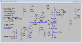
Take a look at the attached diagram. I fiddled around a little with the input stage and did away with the bootstrap cap. It's now also a constant current draw stage (Yes, I copied this from Broskie).
Harmonic content changed a little, but the PSU now sees only a pure constant DC load. Also, all stages are now fully dc coupled and no cap anywhere.
With this arrangement, you can null out psu ripple to incredibly low levels (at least in the simu).
Attachments
Ciro,
If you can indulge me in an off-topic question. I know you have a huge experience with OPT and tube amps in general. Did you ever feel that the sound you value can be achieved from an OTL amplifier, or even one with a SS power stage with tube front-end ?
Best OTL amps can be very good when they are connected to the right speakers.
But in my experience even the very best, change their sound quality when you change the speakers.
So it happens that sometimes they sound great sometimes they suck.
OPT coupled tube amps suffer less from this kind of problem.
Also a few solid state constant current amps can sound very good. But they are just as sensitive to the speaker as tubed OTL amps.
Of course this is what I have met in my individual experience.
With L-W, forget about PSU current delivery to the final power stage (which I assume means AC or variable current delivery capability).
With L-W, the power stage is a closed loop, outside of the PSU and consists only of the opt primary, the power tube, and the ultrapath cap.
The PSU sees a pure constant current draw from the power stage.
--------
Take a look at the attached diagram. I fiddled around a little with the input stage and did away with the bootstrap cap. It's now also a constant current draw stage (Yes, I copied this from Broskie).
Harmonic content changed a little, but the PSU now sees only a pure constant DC load. Also, all stages are now fully dc coupled and no cap anywhere.
With this arrangement, you can null out psu ripple to incredibly low levels (at least in the simu).
This is probably the main pro of L-W amps. You do not need to invest a huge amount of money in super quality power transformers, inductors and capacitors.
Decent quality items will work fine.
Member
Joined 2009
Paid Member
With L-W, the power stage is a closed loop, outside of the PSU and consists only of the opt primary, the power tube, and the ultrapath cap.
The L-W does offer B+ noise cancellation but I can't see why it is different from a traditional non-LW topology with regards influence of the power supply regarding the 'closed loop' current comments. I have already posted a comment on this but had no response so I will ask again...
Look at a traditional design, you will see that the 'last cap' on the B+ line in series with the output tube Cathode Bypass cap together provide the same 'closed loop' for signal current. I can see no reason why both approaches can't be designed to work well without 'special' components but I don't see how one is better than the other in this regard ????
Please also realize that there is a reasonable limit to this kind of noise cancellation too. Reducing the DCR on the lundals by running the coils in parallel seemed nice at first, but there was ripple that could not be cancelled out. So I have it back to 30 Ohms per channel now. I'm very very pleased with it.
Of course, elementary. Build a better low DCR supply as in L1/C1/L2/C2. Ls under 20 Ohms. You get the advantages of the peak current delivery, and the extra ripple reduction of two L/Cs, because " not all cancels out ".
What WAS the mVAC when the chokes were in parallel, and now in series, measured ??
Jeff
Member
Joined 2009
Paid Member
Giving something back……
Sheldon ,
I truly appreciated the nice job (and time) you have spent on this LW thread . I will try to reciprocate a bit, in one area where I feel comfortable, tube amp power supplies.
I spent some time last evening, revamping my original quick PSUD of your 801A amp, and I came up with three quick rough initial ALTERNATIVES, for the “stock” 801A’s ringing B+ filter.
Notice please, the final VDC levels simulate differently, ( up to 9 %, voltage-wise ), in all four filters, AND, the fourth filter uses about a 4 or 5% lower high-voltage secondary, to achieve 550 VDC under load.
These 320 mHY chokes are rated at 600 MA., but since there is only 54 mA. through your 801A stereo amp, I used 500 mHY, and sometimes 400 mHY, as a GUESSTIMATE inductance figure in my sims.
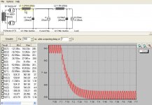
For Sheldon’s STOCK FILTER, I simulate 546 mVAC of ripple, and a 15% current step settle with bad ringing, over 350 mS. I obtained a “computed Z” ( see below, 587.56 VDC minus 583.86 VDC divided by .0045 A. ) of 822 Ohms, and we have 410 Ohms of total series resistances in the chokes.
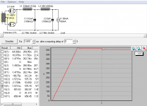
In ALT A , I simply kept your existing chokes, but changed the C amounts, primarily with the goal to minimize ringing of your existing Filter. It displays just a single gentle overshoot, and one third the ripple of the original. Unfortunately, IMHO, the ALT A B+ filter is burdened with 410 Ohms of series DC Resistances and a 70 uF capacitor, 20 more uF than the maximum I prefer to use in such a circuit. Ripple is lowest, at 284 mVAC.
In ALT B, I simulated EDCOR XC-series chokes, which an audio friend tells me did NOT measure as advertised, but worse. It was their nominal L1, 1.5 HY at 17 Ohms and L2, 2 HY at 21 Ohms. He measured Edcor’s 2 HY Ls and found it to be 1.7 HY and 25 Ohms !!! The ALT B topology is a common to both channels L1/C1 and “Y” split for a pair of L2s/C2s, one L2/C2 for each channel
Edcor chokes come stock with “P.U.ny leads”, in and out, and should, IMHO, be end-user DIY replaced with with either two, or a maximum of three, runs of Kimber Kable TCSS 19 AWG wire. This keeps-intact instantaneous PEAK current delivery to the Finals.
ALT B displays a smooth step response, ….always nice to hear. Ripple is 672 mVAC.
( I personally do NOT generally like dealing with Edcor, and prefer using a major established winder, such as Hammond. )
In ALT C, my favorite, I employed four of Hammond’s new 159ZB twelve dollar chokes, ( ZB suffix stands for “Zee Best” ! ). These are rated 320 mHY at only 7.8 Ohms ( !! ) at 600 mA. I simmed them as 400 mHY in PSUD.
For ALT C’s topology , we share the first two Ls between both channels, and then “Y” off, to a left and right channel pair of final L3s and C3s. Ripple is 461 mVAC, manageable. Notice, the step response is smooth, much like ALT B, very good.
What is REALLY great about this filter is we have reduced the undesirable series DCR total from 410 Ohms ( Original and ALT A ) to only 23.4 Ohms. Wow !!
This ALT C has a whopping 17.5 TIMES LESS of series resistances to the Finals!! I suggest this huge reduction to the 801A Finals stage will astound each and every person, listening-wise !! Chokes are driven / passive elements,…… their low DCR matters.
------------------------------------------------------------------------------------------------
NEXT, I will summarize the calculated “Z” of these three “alternative” filters, by looking at the “Centered VDC” ( no ripple content in PSUD measurement ) before and after the 15% current step, which was 0.0045 A. in each case. E divided by I equals R.
ALT A. drops from 596.72 VDC to 593.02 VDC , a 3.70 VDC drop, divided by the current change of .0045 A. equals 822 Ohms, our “ computed Z ” of the FILTER.
ALT B drops from 542.95 VDC to 539.15 VDC, a 3.80 VDC drop, divided by the current change of .0045 A. equals 844 Ohms, a slightly worse “ computed Z ”, than ALT A.
ALT C drops from 550.95 VDC to 548.10 VDC , a 2.75 VDC drop, divided by the current change of .0045 A. equals only 611 Ohms, the very best “computed Z” of all of the three filters.
I normally do not like three L/C sections in series, it can be inherently unstable, often is. In this situation however, there is no doubt as to “me” selecting ALT C., for Sheldon’s amp, out of these four FILTERS we examined. For 550 VDC of B+, it requires a 460 VAC power transformer secondary, instead of 480 VAC.
ALT C has the lowest calculated / simulated Z, by 38%, settles smoothly, has lowest series DCR, and is the least-costly in terms of choke purchases… four twelve dollar Hammond 159ZB 7.8 Ohm chokes. It reflects the design trade-offs “I” consistently find to be the most important, over three decades, in terms of audible performance.
Note: I’ve not yet listened to these new Hammond 159ZBs. The Hammonds’ leads will probably also benefit from a DIYer’s careful re-do.
-------------------------------------------------------------------------------------------------
For C’s in these supplies, consider the new-technology wideband WIMA DC LINK ( or Vishay ) film caps, at industrial prices, about 800 VDC rated for C1, and bypass them with smaller films, etc etc, of your choice.
Thanks for everyone’s continuing help with LW, I may have additional questions.
‘In the end, we all listen to a modulated supply. How well-planned and good is yours ??
Jeff Medwin
Sheldon ,
I truly appreciated the nice job (and time) you have spent on this LW thread . I will try to reciprocate a bit, in one area where I feel comfortable, tube amp power supplies.
I spent some time last evening, revamping my original quick PSUD of your 801A amp, and I came up with three quick rough initial ALTERNATIVES, for the “stock” 801A’s ringing B+ filter.
Notice please, the final VDC levels simulate differently, ( up to 9 %, voltage-wise ), in all four filters, AND, the fourth filter uses about a 4 or 5% lower high-voltage secondary, to achieve 550 VDC under load.
These 320 mHY chokes are rated at 600 MA., but since there is only 54 mA. through your 801A stereo amp, I used 500 mHY, and sometimes 400 mHY, as a GUESSTIMATE inductance figure in my sims.
For Sheldon’s STOCK FILTER, I simulate 546 mVAC of ripple, and a 15% current step settle with bad ringing, over 350 mS. I obtained a “computed Z” ( see below, 587.56 VDC minus 583.86 VDC divided by .0045 A. ) of 822 Ohms, and we have 410 Ohms of total series resistances in the chokes.
In ALT A , I simply kept your existing chokes, but changed the C amounts, primarily with the goal to minimize ringing of your existing Filter. It displays just a single gentle overshoot, and one third the ripple of the original. Unfortunately, IMHO, the ALT A B+ filter is burdened with 410 Ohms of series DC Resistances and a 70 uF capacitor, 20 more uF than the maximum I prefer to use in such a circuit. Ripple is lowest, at 284 mVAC.
In ALT B, I simulated EDCOR XC-series chokes, which an audio friend tells me did NOT measure as advertised, but worse. It was their nominal L1, 1.5 HY at 17 Ohms and L2, 2 HY at 21 Ohms. He measured Edcor’s 2 HY Ls and found it to be 1.7 HY and 25 Ohms !!! The ALT B topology is a common to both channels L1/C1 and “Y” split for a pair of L2s/C2s, one L2/C2 for each channel
Edcor chokes come stock with “P.U.ny leads”, in and out, and should, IMHO, be end-user DIY replaced with with either two, or a maximum of three, runs of Kimber Kable TCSS 19 AWG wire. This keeps-intact instantaneous PEAK current delivery to the Finals.
ALT B displays a smooth step response, ….always nice to hear. Ripple is 672 mVAC.
( I personally do NOT generally like dealing with Edcor, and prefer using a major established winder, such as Hammond. )
In ALT C, my favorite, I employed four of Hammond’s new 159ZB twelve dollar chokes, ( ZB suffix stands for “Zee Best” ! ). These are rated 320 mHY at only 7.8 Ohms ( !! ) at 600 mA. I simmed them as 400 mHY in PSUD.
For ALT C’s topology , we share the first two Ls between both channels, and then “Y” off, to a left and right channel pair of final L3s and C3s. Ripple is 461 mVAC, manageable. Notice, the step response is smooth, much like ALT B, very good.
What is REALLY great about this filter is we have reduced the undesirable series DCR total from 410 Ohms ( Original and ALT A ) to only 23.4 Ohms. Wow !!
This ALT C has a whopping 17.5 TIMES LESS of series resistances to the Finals!! I suggest this huge reduction to the 801A Finals stage will astound each and every person, listening-wise !! Chokes are driven / passive elements,…… their low DCR matters.
------------------------------------------------------------------------------------------------
NEXT, I will summarize the calculated “Z” of these three “alternative” filters, by looking at the “Centered VDC” ( no ripple content in PSUD measurement ) before and after the 15% current step, which was 0.0045 A. in each case. E divided by I equals R.
ALT A. drops from 596.72 VDC to 593.02 VDC , a 3.70 VDC drop, divided by the current change of .0045 A. equals 822 Ohms, our “ computed Z ” of the FILTER.
ALT B drops from 542.95 VDC to 539.15 VDC, a 3.80 VDC drop, divided by the current change of .0045 A. equals 844 Ohms, a slightly worse “ computed Z ”, than ALT A.
ALT C drops from 550.95 VDC to 548.10 VDC , a 2.75 VDC drop, divided by the current change of .0045 A. equals only 611 Ohms, the very best “computed Z” of all of the three filters.
I normally do not like three L/C sections in series, it can be inherently unstable, often is. In this situation however, there is no doubt as to “me” selecting ALT C., for Sheldon’s amp, out of these four FILTERS we examined. For 550 VDC of B+, it requires a 460 VAC power transformer secondary, instead of 480 VAC.
ALT C has the lowest calculated / simulated Z, by 38%, settles smoothly, has lowest series DCR, and is the least-costly in terms of choke purchases… four twelve dollar Hammond 159ZB 7.8 Ohm chokes. It reflects the design trade-offs “I” consistently find to be the most important, over three decades, in terms of audible performance.
Note: I’ve not yet listened to these new Hammond 159ZBs. The Hammonds’ leads will probably also benefit from a DIYer’s careful re-do.
-------------------------------------------------------------------------------------------------
For C’s in these supplies, consider the new-technology wideband WIMA DC LINK ( or Vishay ) film caps, at industrial prices, about 800 VDC rated for C1, and bypass them with smaller films, etc etc, of your choice.
Thanks for everyone’s continuing help with LW, I may have additional questions.
‘In the end, we all listen to a modulated supply. How well-planned and good is yours ??
Jeff Medwin
Attachments
-
 801A STOCK 587 VDC 350 mS. 546 mVAC 410 Ohms series DCR 822 Ohms Z.jpg64 KB · Views: 336
 -
 801A ALT A - 596 VDC 350 mS. 284 mVAC 410 Ohms series DCR 822 Ohms Z.jpg60.8 KB · Views: 298
 -
 801A ALT B - 543 VDC 290 mS. 672 mVAC, 45 Ohms series DCR 844 Ohms Z.jpg63.4 KB · Views: 285
 -
 801A ALT C - 551 VDC 300 mS. 461 mVAC, 23.4 Ohms series DCR 611Ohms Z.jpg65 KB · Views: 293
Jeff,
I appreciate your effort here, but at least please read my posts. The supply you are modeling is NOT what I have used for the 801 Amp.
What is that first 27mA current tap doing in there? This amp uses one, and only one input to the amp. That is modeled by the final current source. Where, pray tell is that other current going? What purpose does it serve? I'm trying to imagine what this supply could be used for and I'm coming up blank. It will model completely differently if you get rid of it.
If you are going to critique my supply and model alternatives, use what I have as a starting point.
Sheldon
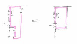
- current loops are equivalent.
They are not, when you include the last PSU cap in the right hand diagram. You will notice then, that no signal AC flows thru the PSU cap.
Assuming that AC levels thru the input stage(s) are negligible, the PSU will deliver constant current to the amp, and constant voltage (excecpt the psu inherent ripple oft course), at any time, and thus is removed from the (audio) equation!
Last edited:
Member
Joined 2009
Paid Member
Yes, but what is a 'PSU cap' ? - the only way your approach makes sense is if you consider a PSU cap as any cap from B+ to ground. But ground is an artificial construct. You are talking current loops.
Member
Joined 2009
Paid Member
I am talking about the last PSU cap, the 2nd L in a LCL psu, if you want.
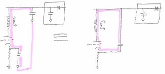
Let's add a 'psu' to both drawings, shown as a diode and a cap inside a box - but we can choose whatever we want to go inside this box and often we have chokes and caps and snubbers, fuses, indicator lights and rectifiers etc. Let's consider it as a box that provides d.c. current.
The signal current in both cases flows through the path of least resistance which in both cases involves a cap hanging off the B+ line. And in both cases we could say that the current flow from the psu box will be constant.
If we choose to improve the isolation between the psu 'box' and the signal current loop we can introduce some resistance, or inductance perhaps. In my solid state amplifiers I have many caps hanging off the power rail and I always put some resistance and often also inductance in the power line so that the signal current and power supply ripple currents are separated.
Attachments
Last edited:
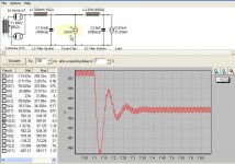
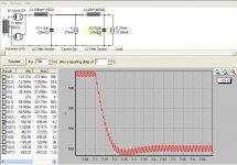
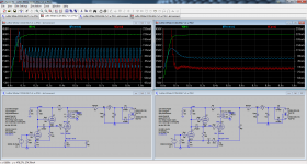
Take a look at the attached comparison, sorry for the size.
On the left is a standard circuit. On the right is the L-W.
The audio section is loaded with a 40 Hz signal.
The PSU provides some 100 Hz hum (50 Hz full wave rectifier).
On the "standard" circuit, the psu cap passes the ac current from the output stage. The current is also passed thru the sense resistor (between psu and audio sections).
On the L-W circuit, the psu cap only sees some 100 Hz ripple current. No audio component here. The current flow thru the sense resistor is almost constant (there's a small 40 Hz audio component - don't know why...).
As a consequence, B+ is modulated with the 40 Hz audio signal in the standard circuit (>5 Vpp @ 40 Hz), while on the L-W circuit, theres virtually no 40 Hz modulation, only the 100 Hz hum (~200 mVpp @ 100 Hz).
The remaining hum is then cancelled out by the L-W topology.
That's what I mean "the psu is taken out of the equation" and probably (part of) the reason why L-W sounds so clean.
I hope you see the difference now.
Cheers,
GB
Attachments
Here:
Your PSUD inputting in Post #274 is incorrect, topology-wise !!
You have a common to BOTH channels power transformer, rectifier, and L1/C1 ONLY. Each 6SN7 draws 2 mA. and each 801A draws 25 mA. So, all three of the parts mentioned in the second sentence draw 54 mA. each, BUT ONLY THOSE 3 parts !!!
After L1/C1, you employ a " Y SPLIT " and use a PAIR of 25 HY chokes to each channel as in :
Left L2/C2 ....and a
Right L2/C2.
But the PSUD sim you inputted does not show two L2s and two Cs, does it ?? No, not at all.
ALL it shows is a single 25 HY choke as L2 and a single C2 value for one channel, doing ALL the amp's 54 mA of current.
The best way to show your supply "as you built it and use it" , or any "Y" split in PSUD2 , is to input it as a single channel power supply after the "Y" and show results for one channel. That is precisely what I have done.
To answer your question, with me putting in a 27 mA. load right after L1/C1, I am showing that the supply was common to both channels, up to that point, and then, ( unlike what you inputted ), I accurately show what is happening to a single channel's B+'s at L2/C2.
There is simply no other way to do this, inputting a "Y" filter in PSUD Sheldon.
The 27 mA. draw I inputted allows us to see how all the parts prior to the "Y SPLIT" handles the 27 mA. TIMES TWO current that is actually running through them. The L2 and C2 for ONE channel accurately shows what is happening to the (only) 27 mA. draw running through those parts ONLY, after the "Y" split.
Go back and look at both of our PSUD inputs, and tell me if you can determine which inputting is most accurate as to how the filter(s) was / were built and are now operating !!!
The other question I have was this, "what are you trying to show and learn", with the simulation you posted and drew for us ??
Finally, I will try to re-do my sims to reflect what you input as 120 Ohms DCR end to end on your HV secondary. That value needs to be many times less Sheldon, I regularly use 9 Ohms, end to center tap.
Jeff Medwin
Last edited:
- Status
- Not open for further replies.
- Home
- Amplifiers
- Tubes / Valves
- 3 direct coupled 2A3 amps