Sheldon,
I am presently contemplating building two different two-stage DC amps, a LW and a conventional Rk bypassed one, and compare the two amps for myself, to learn from direct experience.
A LOT of work, and expense, but ....both should be really nice. I will be able to test them full range on ALTEC A7-800s.
I have a question, when calculating the "cathode to cathode resistance string". Do we use the mu of the input tube "as if its Rk is bypassed", (as I THINK it is shown in the "average characteristic graph "), OR, do we reduce the mu displayed with some formula to represent an "unbypassed Rk tube mu" ?
Sheldon, your original advice was as so, shown next:
"Look at soulmerchant's schema for how to set up the PS noise cancelation. This calculation is simple: The cathode to cathode resistance string, divided by the input cathode value, should be equal to the u of the input tube. The actual optimal value is determined by adjusting by ear, around the calculated value, and will vary some from tube to tube."
-------------------------------------------
What is the best approach to define mu, as a bypassed Rk on the data sheet, ( IF I am interpreting that correctly ), or otherwise ???
TIA,
Jeff Medwin
PS :
As I begin to develop the DC LW designs, I will probably post some of my choices, to have folks confirm I am doing it right.
Initially I am THINKING of using 1/2 of a 6SL7 at about 0.7 mA and 195 VDC Ea, as the plate resistance there is only 52,000 Ohms. For the TAC or Triode Amp Characteristic, Rp only needs to be 208 K Ohms or higher, to get a factor of 4 times happening. I prefer no cathode follower / Darius middle stage added, and I think its easy to get a TAC of 5.5 or so.
Output tubes will be either a 6AH4GT at 25 mA. or a Type 45 at 27 mA. Power supply B+ filter, four Hammond 159ZBs in either amp.
JM
Correction on my "P.S." .
Looking again a second time, plate resistance of a 6SL7GT is 66,000 Ohms at 0.7 mA. and the Ra would need to be 264K minimum at a Triode Amp Characteristic of four times. Easy to do, that computes to a B+ of under 400 VDC. At 450 VDC B+, the Ra becomes about 360K and the TAC is about 5.45 times...likely good enough . My overall B+ ripple will likely be under 0.7 VAC with some of the latest B+ filters I am simming.
What 6SL7 "mu" do I need to accurately use, to compute the cathode to cathode resistance string?? Thanks.
Jeff
Last edited:
Hi Jeff
You are limited by the DC voltage drop across your annode resistor. So the first question is what do you want your bias voltage for your 2a3 to be.
Once you make this calculation, you will realize that your anode resistor with 6SL7 or 12ax7 is just not big enough.... No problem though - just use the second triode in the sleeve as a bootstrapped follower and you will get a "triode characteristic factor" that is more than acceptable.
You can only adjust the mA's so low... I wouldn't really go much lower than a milliamp, but that's more of a personal choice. I chose one milliamp to make the calculations as simple as possible - I'm a lazy physicist 😉
As I noted in a previous post: you can easily get away with up to about 4.0 VAC of ripple using this design. At least that is what my rough experimentation has shown possible. Maybe even more if you are willing to accept a tiny bit of ps hum.
Ian
I'm not sure about the context and exactly what you mean by "mu" here, but valve mu is not affected by cathode degeneration. Add an unbypassed Rk and effective gm drops, effective anode impedance rises and mu stays unchanged.drlowmu said:I have a question, when calculating the "cathode to cathode resistance string". Do we use the mu of the input tube "as if its Rk is bypassed", (as I THINK it is shown in the "average characteristic graph "), OR, do we reduce the mu displayed with some formula to represent an "unbypassed Rk tube mu" ?
Member
Joined 2009
Paid Member
I *think* what Jeff is asking about is the gain, which depends on the mu of the tube as well as other circuit components.
Take the 12AX7 that you (Jeff) are familiar with. With a mu of 100 and a bypassed cathode resistor the gain of a common cathode stage is usually calculated from (mu x Rp)/(Rp + Ra). With Ra (internal tube resistance) of 62.5k and say a plate load resistor of Rp =250k we get a gain of 80.
If the cathode resistor, Rk, is un-bypassed then the resulting degeneration reduces the gain because the effective value of Ra increases according to Ra(eff) = Ra + (mu +1)Rk which if we choose an Rk = 1k5 pushes up Ra(eff) to over $200k and the gain of the stage drops to just over 50.
The other consequence is an increased output impedance when the cathode is un-bypassed and then you start to look at the Cathode Follower inter-stage as a good idea after all. It buffers the input tube from the Miller capacitance of the Final. And because the CF has a light load to drive it shouldn't add much to the sonic signature. Technically however, a source follower is superior because of it's higher gm, but the tube still helps (be careful about heater-cathode voltages).
Last edited:
Interesting Post, 1/2 12AX7 at 0.6 mA., DCed to a 2A3, Measurements
Look at this !!
http://www.audioasylum.com/cgi/t.mpl?f=set&m=79168
Also, Darius chose 0.666 mA. with a 12AX7 input tube, in his three-stage ( bootstrapped cathode follower ) Loftin White 300B amp.
Never say never.
Jeff Medwin
Look at this !!
http://www.audioasylum.com/cgi/t.mpl?f=set&m=79168
Also, Darius chose 0.666 mA. with a 12AX7 input tube, in his three-stage ( bootstrapped cathode follower ) Loftin White 300B amp.
Never say never.
Jeff Medwin
Last edited:
Plot your OP and load line on the 6SL7 plate curves and work out delta Vp/delta Vg
Good, Thanks !!!
JM
Also, Darius chose 0.666 mA. with a 12AX7 input tube, in his three-stage ( bootstrapped cathode follower ) Loftin White 300B amp.
Hi Jeff,
the current thru the input stage is indeed not the problem. The output impedance may be one though. When using huge plate resistors with a 6SL7 or 12AX7, it may give some HF roll off driving the 2A3, even when dc coupled.
An alternative might be the EC86 / PC86, or some triode wired pentodes, if you want to go strictly single input stage.
About you planned builds, you should probably decide on a few key figures first. What B+ voltage do you plan? What will be your power tube, 45, 6AH4GT , 2A3? Input tube 6SL7, 12AX7, or would other types be OK as well?
GB
I have a question, when calculating the "cathode to cathode resistance string". Do we use the mu of the input tube "as if its Rk is bypassed", (as I THINK it is shown in the "average characteristic graph "), OR, do we reduce the mu displayed with some formula to represent an "unbypassed Rk tube mu" ?
You are confusing mu with gain. They are related, but not the same. Mu is a characteristic of the tube and somewhat varies depending on current and voltage, but independent of load line or cathode degeneration (to get an accurate value, find a da sheet with a graph of "average characteristics". Gain is actual gain in a circuit, which depend on bypassing and load line (and feedback, etc.). Use Mu for calculating the cancellation string. By the way, you what to be in a region where the mu is fairly constant.
http://www.mif.pg.gda.pl/homepages/frank/sheets/093/6/6SL7GT.pdf
Sheldon
Last edited:
mu is never the voltage gain....voltage gains of a common cathode circuits are always lower than mu, this is a fact....
You are confusing mu with gain. They are related, but not the same. Mu is a characteristic of the tube and somewhat varies depending on current and voltage, but independent of load line or cathode degeneration (to get an accurate value, find a da sheet with a graph of "average characteristics". Gain is actual gain in a circuit, which depend on bypassing and load line (and feedback, etc.). Use Mu for calculating the cancellation string. By the way, you what to be in a region where the mu is fairly constant.
http://www.mif.pg.gda.pl/homepages/frank/sheets/093/6/6SL7GT.pdf
Sheldon
Thanks Sheldon,
I appreciated your help. I get confused with a lot of EE terms and things, and its nice to have assistance of a friendly type !!
Jeff Medwin
there are a lot that newbies miss out on and this is one of them, i used to think like that also many many years back, fortunately these things can be learned, just cut back on reading adiophoolery and more on the technical materials where meat is a plenty...
lots of gems here free to pick....tubebooks.org - Vintage info from the age of vacuum tubes
lots of gems here free to pick....tubebooks.org - Vintage info from the age of vacuum tubes
mu is never the voltage gain....voltage gains of a common cathode circuits are always lower than mu, this is a fact....
Voltage gain can equal mu. Load the tube with a current source (or better, gyrator) and use a very low Z source voltage source on the cathode.
Sheldon
the current thru the input stage is indeed not the problem. The output impedance may be one though. When using huge plate resistors with a 6SL7 or 12AX7, it may give some HF roll off driving the 2A3, even when dc coupled.
Sorry to quote my own post 😀
I did some calcs and sims, and using some 430k~450k anode resistors on a 6SL7, the HF roll off with a dc coupled 2A3 at 20 kHz was already ~4.0 dB!! Not exactly hi-fi 😉.
So, if you want to go plain single triode driver (resistor loaded) go look somewhere else than 6SL7/12AX7.
Member
Joined 2009
Paid Member
I noticed the same thing in my calculations, although I used a smaller plate load, more current and hence less gain. Then it wasn't so bad. Given that I can't hear past 15kHz this wasn't much of a worry anymore. Now, if I was younger...
Sorry to quote my own post 😀
I did some calcs and sims, and using some 430k~450k anode resistors on a 6SL7, the HF roll off with a dc coupled 2A3 at 20 kHz was already ~4.0 dB!! Not exactly hi-fi 😉.
So, if you want to go plain single triode driver (resistor loaded) go look somewhere else than 6SL7/12AX7.
Look at the simple calcs on my thread to calculate the "triode amp characteristic" factor for 6SL7 when using a 420k Ohm anode resistor, biased for only 0.7mA.
http://www.diyaudio.com/forums/tubes-valves/272548-my-new-iron-single-ended-2a3-4.html
The fact that the triode is not linear does necessarily limit itself to bass response (which is the biggest problem). However the 70-100x gain of 6SL7/12ax7 is still very attractive... The bootstrapped follower solution proposed by Darius is a very good one. Do your simulations use his circuit?
Unfortunately I can't accurately measure such high frequency response with my current oscilloscope... As you know, I prefer to design and actually build things, listen to them and perhaps measure them.
If you can suggest an alternative to 6SL7/12ax7 then someone is bound to pick out all the arguements against it too of course. 😉
Lastly, a good friend of mine noted that a tweeter and crossover network is a waste of money for him. He too can only hear 14kHz on a good day when all is silent... I love his "waste of money" words..
Ian
Last edited:
Sorry to quote my own post 😀
I did some calcs and sims, and using some 430k~450k anode resistors on a 6SL7, the HF roll off with a dc coupled 2A3 at 20 kHz was already ~4.0 dB!! Not exactly hi-fi 😉.
So, if you want to go plain single triode driver (resistor loaded) go look somewhere else than 6SL7/12AX7.
GB,
Thanks !! I think, sir, you were assuming a 2A3, as the Final tube, all along.
Can you do a few calculations for me with the tubes I intend to use, at their operating points ??
The 2A3 has high capacitances, and is listed as
Cg1 = 17 pF
Ca = 11pF.
Cg1-a = 7.5 pF
The 6AH4GT is lower, listed as
Cg1 = 7.0 pF
Ca = 1.7 pF
Cg1-a = 4.4 pF
The driver tube will be 1/2 of a 6SL7GT, operated as follows :
Ia = .0007A.
Ea = 198 VDC
Rp = 66,000 Ohms
Ra = 328.5 K Ohms
Rk = 3.4 K
Ek 2.375 VDC
( Note, for TAC, 328.5K, divided by 66K, is 4.97 times ....LW cancellation is OK, over 4 times )
ALSO GB, the only other Finals tube I was thinking of DCing for this new LW amplifier was a "lovely sounding" Type 45. It has capacitances, ( in the same order as above ), of only 4 pF, 3 pF, and 7 pF.
Any chances of you either / or ( or both - would be most helpful) referring me to the the formulas, or actually computing @ 20 kHZ ..... with these two Finals tubes I am planning on using - at my 6SL7GT's actual defined op point ??
TIA, thanks to everyone !!
Jeff Medwin
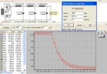
Jeff's Loftin White Power Supply Filter, 6AH4GT DC amp
Well, using a modest Dynaco Stereo 70 power transformer, with all B+ associated leads augmented ( triple Kimber Kable TCSS ) I have finally simmed a LW raw supply I like, that has low DCR as far as B+ series filter resistances...24 Ohms Total, over three L/C sections.
On my home's normally 125 VAC line, I should obtain 439 VDC of B+ with 491 mVAC of ripple, prior to Loftin White hum cancellation. The supply computes to a dynamic Z of 690 Ohms ( 439.26 minus 433.67 is a 5.59 VDC difference, divided by a .0081 A. current step ). It settles from a 15% current step, SMOOTHLY in 200 mS. This is good enough to satisfy me.
The three 750 mHY at 8 Ohm chokes are ones I had custom made for me, six years ago.
Now, to work out the rest of the audio circuit. I can't do much better than what I show, without doing wildly costly custom magnetics for the power supply. Supply / Filter caps will be WIMA DC LINK, all multiple film bypassed.
Jeff Medwin
Attachments
The thing about driving a tube's grid is not just about the frequency response per se, it's also about the perception of 'speed'.
I used to play in bands, and even though we wore hearing protection, I don't hear past 15 kHz.
However I've found that all tubes I've tried driving with a source follower have benefited from it. Some really rather greatly, and some just a bit; but it's always made a distinct improvement.
Even if you can't hear that 20 kHz, or 30 kHz or whatever, it WILL make a difference in how fast the amp will sound; how much perception of impact the sound will have. I find a fast amp to sound markedly more realistic than a slower amp.
For best results, always drive the output tubes' grids with a low impedance; a source follower is easiest and provided the most transparent results. I load it always with a CCS just to have a good current sink as well as a source for the grid.
It's not just about frequency response with the grid.
- Status
- Not open for further replies.
- Home
- Amplifiers
- Tubes / Valves
- 3 direct coupled 2A3 amps