I don't think Jeff wants to hear it, but I'll give it one more shot:
We are not filtering a signal component here we are canceling an added signal that's completely unrelated to the input signal.
Let's try a thought experiment and give a pure sine wave of 120Hz frequency to the input of the amp. Then increase the signal by 10%. The amplitude is 110% of the original. Now let's add 10% of the original signal, but exactly 180 degrees out of phase of the first addition. The first addition and second addition add up to 0 (1 + (-1) = 0), so the original signal is now back to 100%. In this experiment all the signals are in phase, so it's exactly like turning up the volume, then back to the original.
Now use an added signal of a different frequency. This time you will hear two tones blended (just like your ear picks out different instruments from a complex waveform). Then add that same arbitrary signal at the same level as the first, but exactly 180 degrees out of phase (again, 1 plus -1 = 0). The two added signals cancel completely and all you hear is the original 120 Hz signal.
It's as simple as that, but requires perfect phase alignment for perfect cancellation. As a practical matter perfect cancellation is not attainable, but it can be very close - close enough to be below the threshold of audibility for a practical application.
Works for DC too. Measure to battery cells that give slightly different voltages. Put them in series and you get the sum. Put them +to+ or -to- and you will get the difference. If there is no difference the meter will measure zero. You don't have to worry about phase here, but sine waves 180 degrees out of phase add and subtract just like DC (which you can think of as AC with a frequency approaching infinity).
Sheldon
Member
Joined 2009
Paid Member
I assert that the caps in this configuration impact the sound as little as possible.
That’s a fair assertion, I was not putting the issue into context. Signals on the cathode of the input tube are not directly shunted to ground through a traditional bypass cap. And the impedance of the cap + resistor between the two cathodes is far higher than that of the cathode resistor of the input tube. So the cathode resistor dominates and the impact of the “L-W cap” should be much less than that of a traditional bypass cap.
- can you help me, please explain why the L-W can not have an RC filter in the B+ supply feeding the input tube - assume a perfect RC filter so that the B+ supply the input tube is perfectly clean - why is this not good ?
If B+ supply at the input tube was perfectly clean, it would be just as good.
However, in this application real world RC filters are not perfect in two ways. 1st they don't make B+ ripple free, only less. 2nd, if they are filtering, they are introducing phase shift.
#2 means that the residual ripple left by #1 can't be nulled out by the L-W compensation network any more because it's out of phase. For real world cap values, the residual ripple left by #1 will typically be notably more than what can be achieved by nulling it all out with the L-W network.
Play around with the ltspice model I posted and you will see.
BR
GB
Member
Joined 2009
Paid Member
...nulling it all out with the L-W network.
Got it! - good explanation 🙂
Last edited:
If you are correct then I am not appreciating how the L-W works - can you help me, please explain why the L-W can not have an RC filter in the B+ supply feeding the input tube - assume a perfect RC filter so that the B+ supply the input tube is perfectly clean - why is this not good ?
Any time you add a filter you will shift the phase. You can't cancel a waveform with its inverse, unless it's exactly inverse. That means same amplitude, 180 degrees out of phase - nothing more, nothing less.
Now mind you, I'm not saying you can't filter the B+ to the input. But why? All you do is add components. Any ripple you do leave will be out of phase and can't be canceled. Even if you achieve zero ripple at the input plate, you still have to cancel the ripple at the output plate. This LW arrangement achieves virtually complete cancellation because it is adjusted to cancel the sum of the ripple contributions over the entire amp, all in one go. It doesn't need frequent adjustment either, as the mu of the tube is the one thing that's fairly constant over the life of the tube.
It works.
Sheldon
edit: Oops,redundant goldenbeer posted while I composed.
Last edited:
On the first one, I would try taking the signal off the plate of the bottom 6SL7 triode or between the resistor and the choke rather than at the cathode of the top 1/2 of the 6SL7. I have tried it all 3 ways and found that off the plate of the bottom triode measured and sounded best. YMMV.
The middle one looks interesting and is one that I would want to hear. However, there are those that think paralleled triodes are an unimprovement. My experience with paralleled tubes has not been great.
The third one has a cathode follower and YMMV but, I cannot stand the sound of cathode followers and don't put them into circuits by choice. The other reason would be that I don't see how that Cathode Follower can swing enough clean voltage to get full power from the amp(I might be wrong on that one though).
Richard
Any time you add a filter you will shift the phase. You can't cancel a waveform with its inverse, unless it's exactly inverse.
This LW arrangement achieves virtually complete cancellation because it is adjusted to cancel the sum of the ripple contributions over the entire amp, all in one go.
This is why you don't see any RC network in the amp of Darius, Sheldon or mine.
It doesn't need frequent adjustment either, as the mu of the tube is the one thing that's fairly constant over the life of the tube.
This is a big plus. I would add that it applies only to the input/driver tube.
You can swap out the finals if you want, but if you change the input/driver then you will need to adjust the potentiometer. no big deal though.
Ian
Member
Joined 2009
Paid Member
How can I explain this...... it just didn't sound like there was someone playing live music in my living room.
Believe me I made many adjustments and tried many things before simply scrapping that topology altogether. There is no thread here on it because I was never satisfied to share anything of the experience.
This is a pitty because on paper it looks to be as effective as the L-W, uses essentially the same approach and is simpler (once you've tweaked the capacitor values). There's something interesting to learn here about what affects the sound. Do you have any ideas or an opinion as to why it wasn't good ? - did you have access to a range of good quality caps, did you have to make up series-parallel arrangements to get the right ratio of capacitances, did you put a resistor in there anywhere etc. ?
Sheldon !!
You mis read me !!!
" I don't think Jeff wants to hear it, but I'll give it one more shot: "
I am OPEN to all discussion of this, and I will draw in anyone who is willing to comment. NOTE: I do NOT have a background to fully understand all the electrical implications of anything but the most SIMPLE of tube circuitry !!
I am VERY pleased with your contributions to this thread, and others !! I am trying to LEARN, in my own way. That I involve others, like Dennis, Bigun, Goldenbeer, etc, ALL serves to cast light on the subject and provide understanding that I would not EVER BE ABLE TO DO ON MY OWN.
If "I" don't understand things, its HARD to ask the right questions Bigun ASKS good questions.
Do not confuse my lack of EE understanding, with a lack of enthusiasm for the audio arts, or for a lack of sincerity Sheldon...please !! Or worse, dishonesty, or wrong intent.
Do you understand "MY" human dynamic involved here ?? I hope so. THANKS.
Jeff Medwin
On the first one, I would try taking the signal off the plate of the bottom 6SL7 triode or between the resistor and the choke rather than at the cathode of the top 1/2 of the 6SL7. I have tried it all 3 ways and found that off the plate of the bottom triode measured and sounded best. YMMV.
The middle one looks interesting and is one that I would want to hear. However, there are those that think paralleled triodes are an unimprovement. My experience with paralleled tubes has not been great.
The third one has a cathode follower and YMMV but, I cannot stand the sound of cathode followers and don't put them into circuits by choice. The other reason would be that I don't see how that Cathode Follower can swing enough clean voltage to get full power from the amp(I might be wrong on that one though).
Richard
Hi Richard,
Thanks for commenting, BUT, to WHAT specific numbered post are you referring in your comments !!
Regards,
Jeff Medwin
You mis read me !!!
" I don't think Jeff wants to hear it, but I'll give it one more shot: "
I am OPEN to all discussion of this, and I will draw in anyone who is willing to comment. NOTE: I do NOT have a background to fully understand all the electrical implications of anything but the most SIMPLE of tube circuitry !!
Jeff Medwin
In the prior post, it sounded like you were signing off. If you are still interested, I'll (we'll) explain as best I can to your questions.
This is a deceptively simple circuit in terms of part count. But the design is much more clever that it appears at first glance. Here's my amp(BTW, recognize anything in the power supply? The initial choke maybe? But I didn't take it on faith, I simmed it in PSUD and liked what I saw.):
http://www.diyaudio.com/forums/atta...e-801-amp-801loftin-white-sn7-full-schema.gif
You are not the only one having a hard time wrapping your head around this concept. Bigun hit the key issue, and that's the concept of "ground", which is the normal reference point for each section of an amp - both for DC and AC. Any noise from the power supply is just added to the signal. If you have multiple stages, the noise affects each stage independently and may be in phase or out of phase or shifted in phase relative to other stages. All those noise (or ripple) components are summed and added to the signal. So you have to have very low ripple in stages that pass that noise along.
In this amp, the RC connection between cathodes, combined with the B+ connection of the output cap (AC is returned to B+, instead of "ground") counter balances the effect of PS ripple on the input stage against the ripple effect on the output stage. Since the ripple arrives at the input and output tubes at exactly the same time, you just dial the amount of feedback until the cancellation is total. It's a form of negative feedback - but only for the ripple component. If you continue to dial in more the ripple noise comes back, but opposite in phase to the original. You can see it happen on the scope.
Sheldon
The third one has a cathode follower and YMMV but, I cannot stand the sound of cathode followers and don't put them into circuits by choice. The other reason would be that I don't see how that Cathode Follower can swing enough clean voltage to get full power from the amp(I might be wrong on that one though).
Horses for courses. The cathode follower in this application is in an optimal range and lightly loaded. Counter to the situation where the follower needs to supply relatively high current levels, and a high gm low Mu tube is used, the high mu here makes a better follower.
No problem swinging to full power.
Sheldon
In the prior post, it sounded like you were signing off. If you are still interested, I'll (we'll) explain as best I can to your questions.
This is a deceptively simple circuit in terms of part count. But the design is much more clever that it appears at first glance. Here's my amp(BTW, recognize anything in the power supply? The initial choke maybe? But I didn't take it on faith, I simmed it in PSUD and liked what I saw.):
http://www.diyaudio.com/forums/atta...e-801-amp-801loftin-white-sn7-full-schema.gif
You are not the only one having a hard time wrapping your head around this concept. Bigun hit the key issue, and that's the concept of "ground", which is the normal reference point for each section of an amp - both for DC and AC. Any noise from the power supply is just added to the signal. If you have multiple stages, the noise affects each stage independently and may be in phase or out of phase or shifted in phase relative to other stages. All those noise (or ripple) components are summed and added to the signal. So you have to have very low ripple in stages that pass that noise along.
In this amp, the RC connection between cathodes, combined with the B+ connection of the output cap (AC is returned to B+, instead of "ground") counter balances the effect of PS ripple on the input stage against the ripple effect on the output stage. Since the ripple arrives at the input and output tubes at exactly the same time, you just dial the amount of feedback until the cancellation is total. It's a form of negative feedback - but only for the ripple component. If you continue to dial in more the ripple noise comes back, but opposite in phase to the original. You can see it happen on the scope.
Sheldon
Ha ha,
You commented " Here's my amp (BTW, recognize anything in the power supply? The initial choke maybe? But I didn't take it on faith, I simmed it in PSUD and liked what I saw.): "
Oh yes Sheldon, I noticed that immediately and chuckled for a moment or two.
There is a new player on the block, all of about 12 dollars. Hammond 159ZB. I believe its only 7.8 Ohms DCR !!! Instead of 10 Ohms. Have not measured or heard it, but I bet it will be fine !!! Maybe the ZB suffix stands for Zee Best ??
On a LSES supply, where L1=L2 and C1<C2, two ZBs would do a single Type 45 or 2A3 Finals stage just fine.
Cheers, don't give up please .... on any of us. This is getting to be superbly interesting .
Jeff Medwin
This is a pitty because on paper it looks to be as effective as the L-W, uses essentially the same approach and is simpler (once you've tweaked the capacitor values). There's something interesting to learn here about what affects the sound. Do you have any ideas or an opinion as to why it wasn't good ? - did you have access to a range of good quality caps, did you have to make up series-parallel arrangements to get the right ratio of capacitances, did you put a resistor in there anywhere etc. ?
Lots of things look good on paper.
Ha ha,
You commented " Here's my amp (BTW, recognize anything in the power supply? The initial choke maybe? But I didn't take it on faith, I simmed it in PSUD and liked what I saw.): "
Oh yes Sheldon, I noticed that immediately and chuckled for a moment or two.
There is a new player on the block, all of about 12 dollars. Hammond 159ZB. I believe its only 7.8 Ohms DCR !!! Instead of 10 Ohms. Have not measured or heard it, but I bet it will be fine !!! Maybe the ZB suffix stands for Zee Best ??
On a LSES supply, where L1=L2 and C1<C2, two ZBs would do a single Type 45 or 2A3 Finals stage just fine.
Cheers, don't give up please .... on any of us. This is getting to be superbly interesting .
Jeff Medwin
I am tempted to try this too. I just need some time to build some more. Maybe this weekend...
I am tempted to try this too. I just need some time to build some more. Maybe this weekend...
To the best of my present knowledge, you can't use this on LW, because the ripple will ONLY be low enough for the 2A3 stage, ( below 850 mVAC ) but many hundred times too high for the Input stage ( where I like 1 or 2 mVAC.)
Sheldon tells us " NO decoupling" of the supply between these two stages, and I "see" his point.
THIS is a separate challenge I have not yet figured how to overcome. I can't handle over 20 Ohms DCR in Ls to Finals .
The one part shunt regulator is just a draw down resistor, B+ to ground, Mills MRA-12.
Jeff Medwin
I think you need to re-read what sheldon has written a few more times. Take your time to do it. 🙂
Imagine this, the whole amp is swinging in phase with the noise of the power supply. All of it. All triodes, annodes and cathodes, everything. ok?
Now, if you are an AC signal, would you notice that you are swinging? nope...
If you try to filter the input, you will mess it all up. It won't work. It won't be swinging with the rest of the amp and it will definitley sound bad....
Due to the directly coupled design, all triodes swing together so tightly too, so there is only one short path of least resistance for that AC signal. Its so simple and beautiful.
The "triode characteristic factor" helps us when designing that path of least resistance.
BTW here is an added bonus: if you have slightly noisy mains then that might just be cancelled out too. 😉
Ian
Last edited:
I think you need to re-read what sheldon has written a few more times. Take your time to do it. 🙂
Imagine this, the whole amp is swinging in phase with the noise of the power supply. All of it. All triodes, annodes and cathodes, everything. ok?
Now, if you are an AC signal, would you notice that you are swinging? nope...
If you try to filter the input, you will mess it all up. It won't work. It won't be swinging with the rest of the amp in phase and it will definitley sound bad....
Due to the directly coupled design, all triodes swing together so tightly too, so there is only one short path of least resistance for that AC signal.
The "triode characteristic factor" helps us when designing that path.
BTW here is an added bonus: if you have slightly noisy mains then that might just be cancelled out too. 😉
Ian
Ian,
I wasn't thinking in terms of ripple reduction, as much as "fast" PEAK INSTANTANEOUS current delivery to the Finals stage. Chokes over 20 Ohms preclude that in my experience and at my present understanding level. You recently HEARD this effect when you lowered the DCR on your Lundahls!!
MAYBE a LW will work with 800 mVAC on the B+ feeding the amp, maybe ??? The INPUT stage, in my experiences, needs LOW ripple, under 2 mVAC !! Comments ?
Jeff Medwin
Last edited:
Worried about power supply noise? Check out the rudimentary supply on the original - a single diode (not even a rectifier), small PS cap. Ripple anyone? But low noise at the output. It does use a pentode on the input, so that stage is less affected by ripple than a triode, but not much different with the bootstrapped follower.
Now, I wouldn't recommend something this simple for the supply, because the cancellation will be very sensitive to getting exactly at the null. Nevertheless, it demonstrates the effectiveness of the design. One volt ripple will be no problem, but doesn't hurt to be quieter.
Sheldon
http://1.bp.blogspot.com/_oCEpds9Yo.../Loftin_White_Feb_1930_Radionews_Page_704.jpg
Edit: Ripple for the 801 supply is around 0.4V
Last edited:
Worried about power supply noise? Check out the rudimentary supply on the original - a single diode (not even a rectifier), small PS cap. Ripple anyone? But low noise at the output. It does use a pentode on the input, so that stage is less affected by ripple than a triode, but not much different with the bootstrapped follower.
Now, I wouldn't recommend something this simple for the supply, because the cancellation will be very sensitive to getting exactly at the null. Nevertheless, it demonstrates the effectiveness of the design. One volt ripple will be no problem, but doesn't hurt to be quieter.
Sheldon
Loftin_White_Feb_1930_Radionews_Page_704.jpg (image)
Edit: Ripple for the 801 supply is around 0.4V
Hello Sheldon,
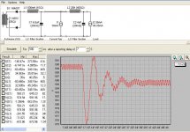
Perhaps off subject, maybe not ! When I just modeled PSUD2 your supply, guessing at values, I got over 1.2 VAC of simulated ripple, and it rings - a whole lot!!! Ringing is a problem I think. I have no way to sim a solid state and tube rectifier in parallel, but the ringing shows up with either device rectifying, on a 15% current step at 7.1 seconds.
I usually look for a smooth and somewhat quick recovery to a step test simulation.
For example, view the Dyna ST-70 Power Transformered DC 1/2 12AX7 - 6AH4GT amp, with perhaps similar current draw, 74 mA TOTAL for stereo. Your supply has about 410 Ohm of series resistances and my "kluge" has about 20 Ohms of series resistances.
Jeff
Attachments

Last edited:
- Status
- Not open for further replies.
- Home
- Amplifiers
- Tubes / Valves
- 3 direct coupled 2A3 amps