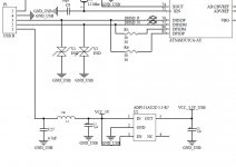
The diode pads have standard 2.54mm pitch spacing, you can put in whatever style diodes you like. With the 330 ohm series resistors, the LED current is about 7mA.
I am putting together my own front and back panel drilling files, will post the dimensions soon.
Perfect!
The output voltage to the frontpanel leds is 3.3v i guess? So led current should depend on what leds you use. I'm probably going to put blue leds there, and if it's 3.3v to them, it's usually a bit looking around before finding low voltage blue ones (they are usually 3.5v approx).
By the way, are they feed with the same supply as the TORX receiver?
The frontpanel LEDS are powered by 3.3V with 330R series resistors. The resulting brightness is fairly soft with standard green and red LEDs that I tried. If you prefer burn-your-eyes-out indicator brightness, you may want to reduce the series resistance by adding some parallel resistors, or short them completely for 3.3-3.5V LEDs.Perfect!
The output voltage to the frontpanel leds is 3.3v i guess? So led current should depend on what leds you use. I'm probably going to put blue leds there, and if it's 3.3v to them, it's usually a bit looking around before finding low voltage blue ones (they are usually 3.5v approx).
Yes.By the way, are they feed with the same supply as the TORX receiver?
I am currently powering the DAC from a +/- 15V supply (because I had it lying around), which is at the upper voltage range. The 3.3V regulator runs quite warm with the 330R LED series resistors. If you put more current through the LEDs, check the regulator temperature. If you run the DAC at the recommended <=12V DC voltage, this should be less of an issue.
If you want to use relatively high current LEDs, it may be necessary to stick a small heatsink such as this one, onto the 3.3V regulator.
Last edited:
I just received the boards this morning, looks great !
What's the input voltage to the default 1117 series 3.3V regulator that you've replaced with a TPS7A4700 ?
Maybe I'll try an ADM7150 instead of the 1117.
What's the input voltage to the default 1117 series 3.3V regulator that you've replaced with a TPS7A4700 ?
Maybe I'll try an ADM7150 instead of the 1117.
I just received the boards this morning, looks great !
What's the input voltage to the default 1117 series 3.3V regulator that you've replaced with a TPS7A4700 ?
Maybe I'll try an ADM7150 instead of the 1117.
The input voltage is whatever the DAC is powered with. 15V in my case, 12V would be more optimal. ADM7150 is rated up to 16V, so it should be ok.
All the boards for this GB round have been shipped and the paypal transactions have been marked as shipped.
More boards can be produced if there is enough interest. Please send me a PM or sign up here for the interest list.
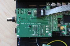
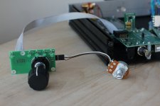
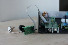
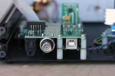
Here are some pictures of a fully built production board mounted on DAM1021.
More boards can be produced if there is enough interest. Please send me a PM or sign up here for the interest list.
Here are some pictures of a fully built production board mounted on DAM1021.
Attachments
Hi. I have a question regarding the Amanero supply using the GB Input PCB. I just want to confirm that in addition to the Dac 7V,10VA transformer, we need an other supply for the Amanero.
I also want to confirm that the Amanero needs an external 3.3Vdc supply, anyone knows the supply current needed? I was thinking to use Salas Reflecktor-D shunt supply for that.
Thanks in advance, any information appreciated.
I also want to confirm that the Amanero needs an external 3.3Vdc supply, anyone knows the supply current needed? I was thinking to use Salas Reflecktor-D shunt supply for that.
Thanks in advance, any information appreciated.
Hi. I have a question regarding the Amanero supply using the GB Input PCB. I just want to confirm that in addition to the Dac 7V,10VA transformer, we need an other supply for the Amanero.
I also want to confirm that the Amanero needs an external 3.3Vdc supply, anyone knows the supply current needed? I was thinking to use Salas Reflecktor-D shunt supply for that.
Thanks in advance, any information appreciated.
The amanero does have it's own supply through USB power, so you won't need any additional 3.3v supply. BUT you can remove one LDO from the amanero pcb and power it with external 3.3v supply if you want.
Yes, you are right. Myself i will use the USB power, since there is reclocking, the psu on the usb-i2s converer isn't that important, i think it's a bit overkill using high end psu before the isolator/fifo. But of course you are free to try and maybe compare!
As Rollee2k already said, there is no need to provide any external power to the input board. Amanero and the dirty side of tHe isolators use power from USB bus, and the other components are powered by the unregulated PWR+ line of DAM1021.
I believe the quality of power for the isolated side will not be very important, and intend to use USB bus power.
However, if you want to try, external power for amanero and isolators can be suplied throgh the duplicated pins of the amanero connector after appropriate modification of the Amanero.
I believe the quality of power for the isolated side will not be very important, and intend to use USB bus power.
However, if you want to try, external power for amanero and isolators can be suplied throgh the duplicated pins of the amanero connector after appropriate modification of the Amanero.
Thanks normundss. This is what I really like about your design, it is so versatile 😉 Thanks again for your hard work.
Has anyone found a U.S. in-stock source for the rotary switch? Mouser lists it, but with a very long lead time on backorder. I think I found an equivalent from Digikey, but that is also not in stock. Thanks - Pat
- Home
- Group Buys
- Input and switch boards for Soekris DAM1021 DAC