Looks real good , jeff !!
Your (and Val's) creation saved me more grief today. Came home to red flashing
lights !! 😱
Kid's wanted louder rock while I was gone , must of done something (short) while
hooking up more speakers (have lot's of those).
So , this project "saves butts" on a day to day basis. Whether it is my stupidity or
youthful enthusiasm.
Thanks , guys ..... Really !!
OS

Hi folks,
I was conversing with Valery in his amplifier thread [CF-FET V2.0 front-end - going high-tech (SMD)] and he suggested that he was contemplating a revision/improvement for this protection design. I can offer something/ideas I designed a while back but never did fab it. It was designed for no controller, but it can be upgraded to add controller and protection ckts as that would be a logical next step to make it a fully functioning smart protection circuit. I will include the schamatic/assy dwg just so you see what i came up with.
I was conversing with Valery in his amplifier thread [CF-FET V2.0 front-end - going high-tech (SMD)] and he suggested that he was contemplating a revision/improvement for this protection design. I can offer something/ideas I designed a while back but never did fab it. It was designed for no controller, but it can be upgraded to add controller and protection ckts as that would be a logical next step to make it a fully functioning smart protection circuit. I will include the schamatic/assy dwg just so you see what i came up with.
Attachments
Hi folks,
I was conversing with Valery in his amplifier thread [CF-FET V2.0 front-end - going high-tech (SMD)] and he suggested that he was contemplating a revision/improvement for this protection design. I can offer something/ideas I designed a while back but never did fab it. It was designed for no controller, but it can be upgraded to add controller and protection ckts as that would be a logical next step to make it a fully functioning smart protection circuit. I will include the schamatic/assy dwg just so you see what i came up with.
Looks good , Rsavas. But this way - was were this project was in the beginning.
Now , paralleled relays - timed /scripted use of just 1 relay for full AC on.
In series, both coils would have to be on. Harder on the poor little 7812 ...
(or any other regulator 🙂 .
Don't need any arc suppression caps across the contacts , as inrush
starts out at low current and full AC switches at 90+% full rail
(very little surge here , as well).
If Jeff creates the big FET relays - an even more ideal setup.
(I like the "old school" auto relays - personally).
PS - I see the ESP audio ground clamp - nice. Add a .01u across
R1 for RF attenuation.
OS
trying to decipher 🙂But this way - was were this project was in the beginning.
All the rest of your ideas, I agree with and will add if i ever make something out of it. I took some more time to review Val's design. It would be nice to add all of it's functionality into my design.
Val is talking about smt, not sure why he wants/needs to do it, space?. Looks fine the way it is.
Thanks Val for sending me the code!!
Last edited:
Hi Rick - yes, I was thinking about probably saving space even further, also - from my first experience with mounting SMT, maybe not optimal yet - I like it. Especially, having the design pretty much refined (not necessary to tune-up, change components). It became pretty much a "product" 🙂
Note the "hardware acceleration" and certain redundancy in this circuit - I thought carefully about making it really reliable, especially for saving the speakers. But it saved some output devices on my test bench too 😛
Jeff's protected PSU board (rails quick shut-down) compliments to the reliability. Now it's really safe. I'm going to add it to my current build as well.
Welcome 😉
About smd ....
I saw your work !! SMD god !!
SMD is good for something like this protection board , where it is "busy" 😀
(integrating a lot of functions , inrush/protection/ac/remote).
You would need 2 or more Ebay boards to do all this ! 🙂
Amps .... well , the choices get slimmer for through-hole as the SMD
choices grow (especially for mosfets).
Analog Output stages seem to need to be through-hole (for now).
PS - You got the code. Yes , 90% of this "wonder" is the code.
I'm 2 versions ahead now - 2 new indicator outputs and the
original indicator is my choice of input or output. Protection
alarms can also be self resetting.
No need to cut traces or
revise circuits - like some modern cars ! 🙂 (tesla !!)
OS
trying to decipher 🙂
All the rest of your ideas, I agree with and will add if i ever make something out of it. I took some more time to review Val's design. It would be nice to add all of it's functionality into my design.
Val is talking about smt, not sure why he wants/needs to do it, space?. Looks fine the way it is.
Thanks Val for sending me the code!!
I saw your work !! SMD god !!
SMD is good for something like this protection board , where it is "busy" 😀
(integrating a lot of functions , inrush/protection/ac/remote).
You would need 2 or more Ebay boards to do all this ! 🙂
Amps .... well , the choices get slimmer for through-hole as the SMD
choices grow (especially for mosfets).
Analog Output stages seem to need to be through-hole (for now).
PS - You got the code. Yes , 90% of this "wonder" is the code.
I'm 2 versions ahead now - 2 new indicator outputs and the
original indicator is my choice of input or output. Protection
alarms can also be self resetting.
No need to cut traces or
revise circuits - like some modern cars ! 🙂 (tesla !!)
OS
Thanks OS & Valery, hello Jeff and other followers.
Once i load the code into jedit, it comes alive and I can follow it just fine. Val your code looks good, it must be, it works!!
Making the logic 3.3V buys nothing, other than add an extra layer of complication. Definitely stay with a mega mcu at 5V.
OS, I agree, for a audio power amp, smt does not buy you much, maybe it can be used for the input stage which uses small sig devices. One thing I do like about using a sot23 package is that the mfg's standardized on the pin assignments = relief. There is no advantage to making a smt package for a TO-264 type device, considering it is to be attached to a heatsink anyways. THT adds strength to a solder joint, which is what one wants.
I can think of some possible additions for features
1) A clipping indicator
2) A output signal level indicator, who does not like flashing lights 🙂 voltage level is the easiest. Making a watt-meter would be a deluxe feature. Measuring the current would be a challenge, especially if one wants to sense/monitor across the emitter ballast resistors.
3) Jeff's additions
I recall member "Esperado" submitted his protection design a while back. Maybe it can be reviewed it to see if he had any good ideas/features that can be included.
Andrew "Bonsai" offered his MOSFET/SSR speaker relay design "http://hifisonix.com/"
Solid State Loudspeaker Relay, white paper describes it.
Rick
The board is already measuring current on the emitter resistors through an optoisolator but it's just turning on at a preset trip point for now. I'm working on isolating an analogue measurement with precision optocouplers among my million other ventures on the go right now.
We have studied Esperado's protection design. That's where my SS relay concept came from.
We have studied Esperado's protection design. That's where my SS relay concept came from.
Hi,
TO : Asavas
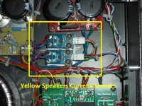
Asavas if you want to read the output current it is easy using the hall effects ACS7xx from Allegro MicroSystems. I am using it to read the speaker current output and shutdown if the current output to the speaker it is too high. The output it is analog voltage proportional to the current. Also it read AC-DC +/- current. To read it you use one of the analog input from the Arduino. They come in 5,12,20,50,100 and 200 amps sizes. You can buy them in Ebay already in a module for few bucks depending of the current. Attached it is a picture showing the current sensor modules installed in my LM3886 amplifier.
TO : Asavas
Asavas if you want to read the output current it is easy using the hall effects ACS7xx from Allegro MicroSystems. I am using it to read the speaker current output and shutdown if the current output to the speaker it is too high. The output it is analog voltage proportional to the current. Also it read AC-DC +/- current. To read it you use one of the analog input from the Arduino. They come in 5,12,20,50,100 and 200 amps sizes. You can buy them in Ebay already in a module for few bucks depending of the current. Attached it is a picture showing the current sensor modules installed in my LM3886 amplifier.
Attachments
Clip indicator -
Most of the slewmaster cascoded VAS's (input stage) have LED's.
The LED Vf will "fold" instantly at the onset of clipping. Since the IPS's
run a couple volts lower than the OPS , the cascode clip is the
first to show.
A dual opto - like an sdt800 , replacing the cascode led's , would detect
clipping real fast.
To integrate this with the control board ..... too many clipping events
within X microseconds could be an alarm , for example. Or a single
event that lasted too long ( a hard clip).
I have one extra input (former led out) , just jumper D10/R21 for an input.
Reassign "pinmode" for atmega D4 - done. No cut traces.
OS
I'm thinking of possibly moving the SS speaker relays right to the output binding posts instead of on the protection board itself. It can't hurt to keep the speaker leads as short as possible to help eliminate noise in the amp. Does everyone use 3/4" centers on their binding posts or are they all different sizes?
I've seen the DC detector also right at the binding posts as well. I believe that 3/4" centres are common but not guaranteed.
I've seen the DC detector also right at the binding posts as well. I believe that 3/4" centres are common but not guaranteed.
I think I'll still be leaving the DC detector on the main board. There shouldn't be enough current flow on the signal wire to cause any noise.
What could actually be gathered on a small PCB close to the output terminals, along with the SS relays - Thiele/Zobel networks. They work well there, allowing smaller OPS PCB at the same time.
What could actually be gathered on a small PCB close to the output terminals, along with the SS relays - Thiele/Zobel networks. They work well there, allowing smaller OPS PCB at the same time.
I could put some pads for the Thiele/Zobel networks. Jason's got me thinking about the DC detector circuit there now too. Tauro0221's hall effect could go there as well. The 50 amp version looks cool.🙄
Make a circuit diagram.it is useful ,a picture is beter than 1000 words.🙂mClip indicator -
Most of the slewmaster cascoded VAS's (input stage) have LED's.
The LED Vf will "fold" instantly at the onset of clipping. Since the IPS's
run a couple volts lower than the OPS , the cascode clip is the
first to show.
A dual opto - like an sdt800 , replacing the cascode led's , would detect
clipping real fast.
To integrate this with the control board ..... too many clipping events
within X microseconds could be an alarm , for example. Or a single
event that lasted too long ( a hard clip).
I have one extra input (former led out) , just jumper D10/R21 for an input.
Reassign "pinmode" for atmega D4 - done. No cut traces.
OS
valery has send me code for arduino.os ,have you a newer version?7
Last edited:
Yes, alarm from a 50-amp sensor indicates you've probably got some problem 😀
50A is overkill but any smaller rating changes the current leads to tiny wire.
Attachments
- Home
- Amplifiers
- Solid State
- How to build a 21st century protection board