Yes, my question is of the same nature - what would be the key advantages? Saving cost? It's rather low anyway. At the same time, shorter connections - better performance. Well, it's possible to opto-decouple most of the lines... Anyway... potentially doable, but... does it make sense?
As a "crazy" idea, it's possible to arrange a control/protection "box", serving a number of channels / amplifiers simultaneously, communicating with them via digital CAN-bus. But again, separate control box in every device gives more flexibility, I believe.
As a "crazy" idea, it's possible to arrange a control/protection "box", serving a number of channels / amplifiers simultaneously, communicating with them via digital CAN-bus. But again, separate control box in every device gives more flexibility, I believe.
The main reason is neither of the amps I have built have much space to mount a board, so an external box seemed very attractive.
The main reason is neither of the amps I have built have much space to mount a board, so an external box seemed very attractive.
I just had the same problem with an amplifier.
I wanted DC protect circuit but no room in amp box.
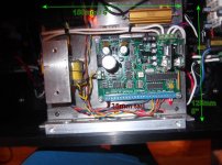
So I bought a ABS box and put in a mains transformer, pcb and 2 jack sockets for speaker lead in/out.
If I had put it in amp box I would have a power supply already made and no enclosure to buy.
The main reason is neither of the amps I have built have much space to mount a board, so an external box seemed very attractive.
I've got the board shrunk down to 3" x 4". With the right choice of capacitors it could be under 1" tall too. It's easy to tuck it in somewhere but it wouldn't be hard to run externally either. 2 wires to RE resistors on each channel, 2 wires to temp sensors on each heat sink. You would need to run mains power through relays and softstart resistor if required. That could be in an external box your amp plugs into. Speaker leads would go out to your protection board and out to your speakers from there. This is basically how I have mine set up on my test bench
Yes , it was worth building my amp twice 😀 and waiting for Jeff's second
round of "magic".
(below) ... I'm just using leftover space over my trafo for both full AC control
and protections.
I do use my old "clunky" previous version for portable use , BTW.
Using it to perfect my selectable alarm "self - resetting" V8 script.
A "smarter" main control loop ~!!
Marsupialx , I could of shrunk down to 125 X 125 X 30mm If I had
less room. I had (an ample) 175mm^2 X 40mm to work with !😱
Edit - would of had to "stash" the 12v trafo somewhere else.
OS
Attachments
I could have gone SMT on everything and really shrunk it but nobody would have wanted to build it. I like soldering in a toaster oven.Yes , it was worth building my amp twice 😀 and waiting for Jeff's second
round of "magic".
(below) ... I'm just using leftover space over my trafo for both full AC control
and protections.
I do use my old "clunky" previous version for portable use , BTW.
Using it to perfect my selectable alarm "self - resetting" V8 script.
A "smarter" main control loop ~!!
Marsupialx , I could of shrunk down to 125 X 125 X 30mm If I had
less room. I had (an ample) 175mm^2 X 40mm to work with !😱
Edit - would of had to "stash" the 12v trafo somewhere else.
OS
I could have gone SMT on everything and really shrunk it but nobody would have wanted to build it. I like soldering in a toaster oven.
SMD resistors would of been MUCH easier than those tiny through holes.
What's with them ?? At that size , what's the purpose ? 🙄
OS
I used to build a lot with 1/8 watt. Then I got sick of drilling all those holes in the PC boards and started using SMT. They do save quite a bit of room on the board though.
Well, using a wise layout with SMT, we would come to the board size, where most of the space would be taken by connection sockets 🙂
Having a few rather compact amp compartments, I was thinking about a different setup.
Main compartment - the amp boards, heatsinks, a few snap-in filter-caps, control / protection board.
Separate box - trafos, main filter cap banks, inrush components - basically, external PSU.
Fat power cable, delivering DC rails to the amp box, as well as ground, and a few control signals back to PSU box. This kind of approach is used in some of the preamps, minimizing EMF effects from the trafos, but with rail connection, thick enough, I believe it will work well for a power amp as well. That cable may be rather short, by the way.
Well, using a wise layout with SMT, we would come to the board size, where most of the space would be taken by connection sockets 🙂
Having a few rather compact amp compartments, I was thinking about a different setup.
Main compartment - the amp boards, heatsinks, a few snap-in filter-caps, control / protection board.
Separate box - trafos, main filter cap banks, inrush components - basically, external PSU.
Fat power cable, delivering DC rails to the amp box, as well as ground, and a few control signals back to PSU box. This kind of approach is used in some of the preamps, minimizing EMF effects from the trafos, but with rail connection, thick enough, I believe it will work well for a power amp as well. That cable may be rather short, by the way.
Hi , val ...
You know , with "21'st century techniques" , having the EMF offenders and our sensitive audio in one case is possible.
-AC cables and rail feed are the worst wire offenders (shield them).
- the toroid has a weak spot at the break of the pri/secondary taps (aim that away from anything).
-using any EI (like the control board trafo) is problematic. It has a larger field than
a 1KVA , in all directions !!
Do like parasound ... trafo in a grain oriented steel metal box , and use a high Q
shielded toroid 12V control board trafo.
My hum is below the input pair noise floor - can't get better that that.
OS
Last edited:
Should I do an SMT version of this? There would only be one socket. All other ICs would be SMT.
Should I do an SMT version of this? There would only be one socket. All other ICs would be SMT.
If you were to make just the resistors SMD's , that would cut assembly time
in half. The next group would be the small signal diodes. Opto's and that
darlington array would be best left DIP , one can optionally socket these to
make for a VERY servicable setup. (not that these components fail often -
but they could ?)
Another idea is to array the 7 - 4.7k pullup resistors ,replace the 2 "clunky"
tip's (relay drivers).
It's really good as is ... just pointing out the things that slowed down my board
stuffing.
OS
I've been using SMT ULN2003 for years and never managed to hurt one. They are safe to go SMD. ICs come off well with a big hot iron anyway. Easier then prying out pins on through hole. The DC detect transistors can be SMD. They are easier to remove than through hole as well if they fail. The relay driver transistors are just driving optos so they aren't handling any current. Is it worth simulating for replacement transistors or just wing it and adjust on the fly?
I've been using SMT ULN2003 for years and never managed to hurt one. They are safe to go SMD. ICs come off well with a big hot iron anyway. Easier then prying out pins on through hole. The DC detect transistors can be SMD. They are easier to remove than through hole as well if they fail. The relay driver transistors are just driving optos so they aren't handling any current. Is it worth simulating for replacement transistors or just wing it and adjust on the fly?
I have not actually used them , but I think SMD equivalents are the same semi dies
as their through hole counterparts , just the package is changed.
Same for IC's , same process ... just a different mold.
I also have seen smd 5551's and mpsa92/42's (mmbt5551 and mmbt92/94).
OS
The only part I'm unsure of is the big TIP devices. I think base current is kind of critical to the circuit. There will likely need to be some changes to resistors in that area.I have not actually used them , but I think SMD equivalents are the same semi dies
as their through hole counterparts , just the package is changed.
Same for IC's , same process ... just a different mold.
I also have seen smd 5551's and mpsa92/42's (mmbt5551 and mmbt92/94).
OS
Last edited:
The only part I'm unsure of is the big TIP devices. I think base current is kind of critical to the circuit. There will likely need to be some changes to resistors in that area.
MMBTA14/16 , mmbta63/65 , or higher current mdj127(exact replacement). plenty of smd
equivalents.
OS
Are boards available? It would be great to try surface mount, as it seems to be the future, if not the present. Through hole is alright. Small is good. Thanks!
I'm just starting to lay out an SMT board. I can send you gerbers for the current board but it isn't tested yet. I should have my testers in a week.
- Home
- Amplifiers
- Solid State
- How to build a 21st century protection board