DejaVu
I didn't start any fires but I did have a few transistor failures. The VAS transistor ran very hot, Q3, BC546. I was using them with a 4 way active x-over so they were not being driven very hard. I had a common power supply driving 4 units and I did get some collapse of the supply rails during heavy bass passages otherwise lots of enjoyment.
Regards Ray
Very good experience with Digi 125 kit, Have been using 7 channel of these for last two + years.
No problem what so ever and very good sound too.
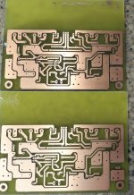
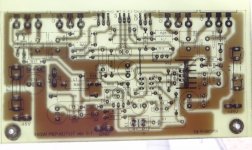
http://www.diyaudio.com/forums/atta...97486580t-digi-125-kit-amplifier-module-2.jpg
http://img151.imageshack.us/img151/8559/img0901x.jpg
No problem what so ever and very good sound too.
http://www.diyaudio.com/forums/atta...97486580t-digi-125-kit-amplifier-module-2.jpg
http://img151.imageshack.us/img151/8559/img0901x.jpg
quality micron 50s with ne5532 preamp
thanks its very high quality,i built it with gasgate paper
just having fun with it🙂 you share,i build thank you
i belive you.
MAX DC SUPPLY 35 O 35 DC
transformer 24 0 24 ac max
thanks its very high quality,i built it with gasgate paper
just having fun with it🙂 you share,i build thank you
i belive you.
Attachments
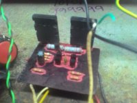
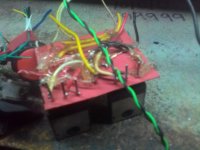
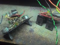
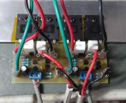
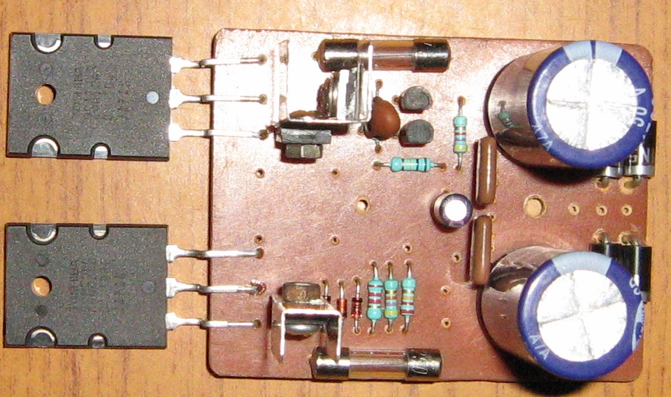
I was intrigued by the little Micron 50S so I etched a pair and built them. When I fired them up, both channels show a -200mV offset. So, I built a spice model so I would have something to compare it too. The spice model shows a -180mV offset. Checking the bias shows that the PNP outputs have about 100mA but the NPN has almost nothing. Maybe this is part of the design but that is too much offset. Maybe one of you who knows better than me can take a look and see what is causing this. I'm attaching a photo and the asc file.
Blessings, Terry
Blessings, Terry
Attachments
I was intrigued by the little Micron 50S so I etched a pair and built them. When I fired them up, both channels show a -200mV offset. So, I built a spice model so I would have something to compare it too. The spice model shows a -180mV offset. Checking the bias shows that the PNP outputs have about 100mA but the NPN has almost nothing. Maybe this is part of the design but that is too much offset. Maybe one of you who knows better than me can take a look and see what is causing this. I'm attaching a photo and the asc file.
Blessings, Terry
Please change these:
R3 = 3K3
R5 = 22K
R6 = 1K
C2 = 100uF
HI Andrew,
Thanks for the welcome. I try to stay busy. 😀
Hi Bimo,
I made those changes in the spice file. The offset is better but the bias drops to 3mA on the PNP and less that 1mA on the NPN. I'm already seeing crossover distortion on the scope. Do you think that will make it worse?
Thanks for the welcome. I try to stay busy. 😀
Hi Bimo,
I made those changes in the spice file. The offset is better but the bias drops to 3mA on the PNP and less that 1mA on the NPN. I'm already seeing crossover distortion on the scope. Do you think that will make it worse?
HI Andrew,
Thanks for the welcome. I try to stay busy. 😀
Hi Bimo,
I made those changes in the spice file. The offset is better but the bias drops to 3mA on the PNP and less that 1mA on the NPN. I'm already seeing crossover distortion on the scope. Do you think that will make it worse?
You can add one dioda and paralel with resistor between D1 and D2. Then adjust value of the resistor to set bias current. Don't set bias current to high, you can enter to thermal runaway. For class B, 1 to 10 mA is enough.
May be you want to build this: http://anistardi.wordpress.com/2014/10/14/perkutut-amplifier/
Talked me into it.
Attachments
Any changes I should know about?
Alternative for Q4: 2SA1381
C2, C10, and C11 should be Silver Mica or Ceramic NP0/COG
C1 is MKP or MKS (usually I use WIMA, because it is cheap).

I'm too cheap too. I will probably just use what I have in the bin. I stopped buying mica a long time ago. I did lots of listening tests and it is my finding that you cannot hear the difference between mica and MLCC. Can't see it on my scope either. I'll build these tomorrow and let you know how it goes.
Blessings, Terry
Blessings, Terry
I'm too cheap too. I will probably just use what I have in the bin. I stopped buying mica a long time ago. I did lots of listening tests and it is my finding that you cannot hear the difference between mica and MLCC. Can't see it on my scope either. I'll build these tomorrow and let you know how it goes.
Blessings, Terry
This is not because of THD or sound quality, but sliver mica and ceramic NP0/COG have almost zero temperature coefficient. We do not want amplifier stability change because the temperature changing.
Of course if you always operate the amplifier in same temperature, it does not matter 🙂
if the MLCC is also NP0/COG, then fine.I'm too cheap too. I will probably just use what I have in the bin. I stopped buying mica a long time ago. I did lots of listening tests and it is my finding that you cannot hear the difference between mica and MLCC. Can't see it on my scope either. I'll build these tomorrow and let you know how it goes.
Blessings, Terry
But MLCC is the assembly into layers. It does not specify the materials.
This amp will likely never be played for hours on end. They are normally played for a couple days and tested through my scope and then set up on my A/B setup and compared against a few of my other amps. Then it will join the other 50 or so amp boards in the closet. This probably doesn't make sense to a lot of people but for me the joy comes from the challenge of building and testing. I already have more amps than I can ever use.
Blessings, Terry
Blessings, Terry
- Status
- Not open for further replies.
- Home
- Amplifiers
- Solid State
- 2SC5200 Power Amplifier