4mV RMS sounds a little different from your earlier claim of 100uV. So let's plug this revised figure into your own math. It looks to be about 32dB worse than your calculation hence the -141dB figure rises to -109dB.
I agree it would be unwise to draw firm conclusions from my quick-and-dirty simulation. However the aim was not to draw any conclusion other than its suggesting to me that your opamp supply isn't competently engineered. After all you had claimed 'low noise regulators' were used - the output noise of LM317 I reckon should be under 0.5mVRMS, admittedly in a 10kHz bandwidth.
I agree it would be unwise to draw firm conclusions from my quick-and-dirty simulation. However the aim was not to draw any conclusion other than its suggesting to me that your opamp supply isn't competently engineered. After all you had claimed 'low noise regulators' were used - the output noise of LM317 I reckon should be under 0.5mVRMS, admittedly in a 10kHz bandwidth.
Last edited:
Given nothing obvious can be seen above the (very low) noise floor what would be the improvement in the measured performance from a regulator regime that you deem 'competent'. I must be missing something as I can't see any obvious space for improvement.
The measured performance doesn't concern me - I'm only concerned about how it sounds. You have the amp, why not try improving the power supply noise by 20dB and see if you notice anything?
I have the boards. I don't have an amp yet or equipment to measure a 20dB drop in the noise floor. I also lack a system where anything else is even close to the mod-86 noise floor. I am also someone who likes to correlate measurements with audible improvments. Dreadfully old school I know, but you know how belief systems affect ones perception...
Dreadfully old school I know, but you know how belief systems affect ones perception...
Sure, preaching to the choir here. Tomchr's demonstrated that marvellously on this thread and his original one in the Vendor's Bazzar 😀
No I am just stating my personal preference. I have no affiliation with Tom other than having bought things off him. I chose to build this board as the cost😛erformance ratio is very high and certainly way better than anything I could do from scratch. I did the whole magic capacitors and flooby dust in my early 20s and currently want something with superlative measured performance as a reference. These are my preferences and other people have other preferences. Takes all sorts to make a world. But you are finding fault objectively and claiming only subjective benefits which is an odd straddling of the preference divide.
And FWIW and I will look at the specs later I suspect the actual THD performance of the THAT1200 is higher than the noise floor in this so for those who can hear 40dB below the accepted minumum for homo sapiens that might be the place to look.
And FWIW and I will look at the specs later I suspect the actual THD performance of the THAT1200 is higher than the noise floor in this so for those who can hear 40dB below the accepted minumum for homo sapiens that might be the place to look.
I took a different approach when working the MyRef which I had explained in that thread. I do plan to explore this more in a new design I am involved in.Time to fire up LTSpice for a quick look-see. I've modelled the LM317L as a 33uH inductor (matching the 4ohm Zout at 20kHz) but have no idea what damping it contributes to the circuit. So if anyone has an estimate for that, I'm all ears. I've put in 0.1R series resistance for now.
The vertical scale is in dB but since the current source is 1A, can be interpreted as dB-ohms. The peak at 50kHz at 25dB-ohms corresponds to the ESR I estimated for the 10uF/50V Panasonic EB output capacitor. The remaining 3 caps are 100nF placed at the pins of the three ICs powered by the LM317L. I've assumed their ESR is negligible.
<edit> My earlier post where I figured the output caps were going to determine the impedance above 20kHz looks to be wrong by more than an octave. I hadn't figured that the Pana EB's ESR was going to be as high as it is. So the regulator's inductive output impedance only gets ameliorated above 50kHz with the current decoupling configuration.
I'm in the process of building a stereo Mod86, PCB's and components arrived, but Mouser (or I 🙂 missed a couple of components in the initial order,waiting on two capacitors now.
Oh, did I mention, I'm a complete newbie.
In the meantime, I had a couple of questions:
1) I'd like to add a volume control, or maybe a preamplifier with a volume control. Any suggestions? (recall, complete newbie, will need schematic, and advice on what types of components to use. I'm game to try to fabricate a small PCB myself using the iron-on method.)
2) It would be nice to integrate a USB input, with an input selector switch. Any suggestions for a decent DAC circuit or board that would work well with this?
If this question would be better in a different thread, please let me know.
Thanks, all.
Ah some signal. Sorry you nearly got lost there. Your questions are good ones but sadly you will get 100 different answers here all of which are valid.
For the DAC the ODAC is a known quantity and affordable. The designer divided opinion until he vanished but it is as good a starting point as any.
For pre-amp it gets more fun. The Pass B1 is cheap and measures well. Mezmerise boards are available along with the FETs from the DIY audio store. BUT its not balanced. No big loss as you still get great CMRR with the mod-86 pseudo balanced links, but if you want the whole hog I don't know of any suitable beginners circuits out there.
My tuppence, others will chip in with their own views.
I'm in the process of building a stereo Mod86, PCB's and components arrived, but Mouser (or I 🙂 missed a couple of components in the initial order,waiting on two capacitors now.
Oh, did I mention, I'm a complete newbie.
In the meantime, I had a couple of questions:
1) I'd like to add a volume control, or maybe a preamplifier with a volume control. Any suggestions? (recall, complete newbie, will need schematic, and advice on what types of components to use. I'm game to try to fabricate a small PCB myself using the iron-on method.)
2) It would be nice to integrate a USB input, with an input selector switch. Any suggestions for a decent DAC circuit or board that would work well with this?
If this question would be better in a different thread, please let me know.
Thanks, all.
Thanks Bill for bumping this one back to life!
There were two caps missing from the original bill of materials, so if you ordered before that was corrected you were short those two parts.
Complete Newbie!

1. Preamp. It would be wise to make a balanced preamp to take full advantage of the balanced amp. By using ICs this is not hard. A simple way to go would be an opamp. The Modulus-86 in stock form has 20dB of gain. Most commercial integrated amps have 40dB of gain, so that should be your target unless you have very sensitive (>94dB,) or very insensitive speakers (<87dB.) While opamps are sometimes poopoo'd by audiophiles, Modulus proves that opamps in the signal path are not a liability when each part is used in a flattering way. All opamps are not interchangeable, nor does any opamp sound the same with different gains and different loads. Finding the happy zone for an opamp will allow it to make great music. Treating an opamp as interchangeable commodity will yield poor results that you won't want to listen to.
Since it is a proven to sound good and have excellent performance, I would just use the same front end from the Modulus-86, that being THAT1200 balanced input IC (0dB gain) feeding two LME49710 opamps set for 20dB gain. The 49710s can be arranged to make a balanced output. The link between the 1200 and the 49710 balanced stage is single ended, so you can put your volume control, tone controls and muting in the SE section. For schematics, just use the specsheet circuit for THAT1200, and use Rod Elliot's balanced output circuit for the 49710s, and whatever other features you want. I recommend Gold Point volume control and source switch, or remote control from Bent Audio.
2. USB input. These USB inputs/DAC kits are well designed and sound excellent. I have not heard their DAC, but I do use the same DAC chip in my DAC and it is also fantastic.
You can find power supply designs everywhere. I personally would make a simple bipolar unregulated PS then regulate it to the desire voltage using Belleson regulators of the appropriate current rating. Simple, cheap, low heat and best performance. Or see Rod Elliot's P05.
You can get a lot of specific design advice about the actual circuits here on diyaudio if you post a new thread once you clarify your intentions and propose a plan/schematic. Use the search function to look for other balanced preamps on diyaudio too.
For those interested in measurements, I've attached the latest. This level of performance is what you can expect if you assemble the boards according to the BOM.
The Modulus-86 is intended as a turnkey analog subsystem. Buy, build, enjoy. For those wishing to modify the MOD86, I strongly recommend reading Appendix A-2 in the design doc.
The performance speaks for itself. The attached measurements were taken with a regular unregulated power supply (toroid transformer, rectifier bridge, 2x22000 µF capacitors).
~Tom
Attachments
-
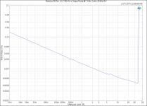 Modulus-86 Rev. 2.0_ THD+N vs Output Power @ 1 kHz, 8 ohm, 20 kHz BW.png38.5 KB · Views: 693
 -
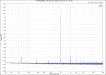 Modulus-86 Rev. 2.0_ Harmonic Spectrum @ 1 kHz, 1 W, 8 ohm.png38.6 KB · Views: 688
 -
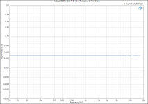 Modulus-86 Rev. 2.0_ THD+N vs Frequency @ 1 W, 8 ohm.png35.8 KB · Views: 687
 -
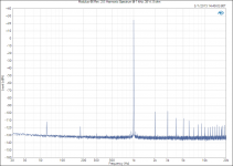 Modulus-86 Rev. 2.0_ Harmonic Spectrum @ 1 kHz, 38 W, 8 ohm.png40.7 KB · Views: 687
 -
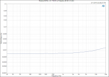 Modulus-86 Rev. 2.0_ THD+N vs Frequency @ 38 W, 8 ohm.png36.7 KB · Views: 684
 -
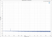 Modulus-86 Rev. 2.0_ Noise Floor.png34.5 KB · Views: 189
Thanks Bill for bumping this one back to life!
+1
There were two caps missing from the original bill of materials, so if you ordered before that was corrected you were short those two parts.
That was addressed way back in January. There's a 4-5 day window in early 2015 where the Mouser BOM was incorrect. That's all fixed.
1. Preamp. It would be wise to make a balanced preamp to take full advantage of the balanced amp. By using ICs this is not hard.
THAT1646 or THAT1606 + THAT2181.... That would make a NICE OldSkool™ Preamp.
You could also use a PGA2320 with a THAT1646/THAT1606 output driver.
Or... A volume pot with a THAT1646/THAT1606 output driver. That would be a pretty sweet AlmostPassive™ Preamp.
(Pardon the MarketingSpeek™. It's that kind of morning... 🙂)
The Modulus-86 in stock form has 20dB of gain. Most commercial integrated amps have 40dB of gain, so that should be your target unless you have very sensitive (>94dB,) or very insensitive speakers (<87dB.)
The THX standard says 26 dB gain (20x). I chose 20 dB because I get better performance and for hifi, the additional gain is not needed.
The Modulus-86 Rev. 2.0 requires 1.75 V RMS to reach clipping on ±28 V rails. The Modulus-86, slightly less (1.65 V RMS if memory serves). Modern hifi gear outputs 2 V RMS, so you don't need any additional gain to reach clipping.
To get the best SNR, you actually want as little gain in the system as you can get away with. The common practice of attenuating the signal in the preamp only to amplify it in the power amp really hurts the SNR.
My PGA2320-based preamp has a readout of the preamp gain in dB. For normal listening levels using MOD86 Rev. 1.0, 85 dB/W*m efficient speakers, listening position about 2 m from the speakers, my preamp sits at -45 ~ -40 dB. For more critical listening, I'm running the preamp in the -30ies. I see no need for increasing the gain in the MOD86.
While opamps are sometimes poopoo'd by audiophiles, Modulus proves that opamps in the signal path are not a liability when each part is used in a flattering way.
I think a lot of the poo-pooing of op-amps stems from the days of the µA741. That part was so performance limited that it severely degraded the sound quality. Thankfully, we've learned a thing or two since the 1970ies... 🙂 The concern was valid then, but assuming good circuit design, it really isn't valid today.
You can find power supply designs everywhere.
If you buy the Modulus-86 boards, you can also just copy the ±15 V supply section from the schematic and use that. Or... If you build the volume control into the same chassis as the MOD86, you could tap off of the ±15 V supply already present in the MOD86. Options, options.
I personally would make a simple bipolar unregulated PS then regulate it to the desire voltage using Belleson regulators of the appropriate current rating. Simple, cheap, low heat and best performance.
I'd be surprised if you can beat the performance of modern ICs, though...
~Tom
At last, an amp designer with a realistic approach to gain. Most modern amps have far too much in my experience. My latest DAC can output 2.25 V which makes the usable range of potentiometer travel very small before it goes deafening. I salute you sir, well done.
At last, an amp designer with a realistic approach to gain. Most modern amps have far too much in my experience. My latest DAC can output 2.25 V which makes the usable range of potentiometer travel very small before it goes deafening. I salute you sir, well done.
My point exactly. Thank you.
~Tom
I agree to that as well. We only need enough gain to drive max output when the signal source is at max output. Mostly, we need some attenuation. Most users I have come into contact with feel uncomfortable turning the volume up past 12, it will be an education process.
Not quite. A number of my recent audio dabblings have not had enough gain for some recordings, and this has been a bit frustrating. There are recordings out there that have been mastered at very low average levels - nothing from the last twenty years, of course!! 🙄 - and more gain would have been very nice!
Listening to an album with volume at maximum, and getting sound levels about that of a TV set adjusted for average viewing is not helpful - a bit more adjustment in reserve should not be discarded lightly ...
Listening to an album with volume at maximum, and getting sound levels about that of a TV set adjusted for average viewing is not helpful - a bit more adjustment in reserve should not be discarded lightly ...
What is the input impedance of the Modulus-86 rev.1 ? I was wondering if the relatively high 560 Ohm output impedance of a miniDSP unit I would want to drive it with would be a satisfactory match.
Thanks, /path
Thanks, /path
Then add an optional (switchable) +6dB/+12dB gain stage between the low output source and the power amplifier.Not quite. A number of my recent audio dabblings have not had enough gain for some recordings, and this has been a bit frustrating. There are recordings out there that have been mastered at very low average levels - nothing from the last twenty years, of course!! 🙄 - and more gain would have been very nice!
Listening to an album with volume at maximum, and getting sound levels about that of a TV set adjusted for average viewing is not helpful - a bit more adjustment in reserve should not be discarded lightly ...
There are no engineering/sound quality reasons to increase the gain of the power amp because a few of your sources are low output types.
No, the source remains the same - CD, Red Book material from the same analogue circuitry. It's a simple fact of life that recent rock recordings will deafen you in 5 minutes, at 3/4 volume; whereas some early, older style CD transfers are barely adequate at maximum volume!
It just means that there needs to be sufficient gain, so that the attenuator never has to be set at 0dB - always just a little in reserve.
It just means that there needs to be sufficient gain, so that the attenuator never has to be set at 0dB - always just a little in reserve.
Differential input impedance is 48k so should be no problem at all.
Great! Thanks for your confirmation. I have yet to find the time to build the amps.
- Home
- Amplifiers
- Chip Amps
- Modulus-86 build thread