Actually re-reading your contributions were discussed and when presented with some calculations you were unable to defend your theory so resorted to accusing Tom of having not done his calculations correctly. In your own words "after all I'm no authority here".
We would welcome some workings from you, or measurements to show what improvements you can get from reworking the power supply to the THAT chip.
FWIW I was re-reading Bruno P's 'G-word' article the other day and noticed that he considered the THAT 12xx series for that pre-amp but decided it had too much distortion for the application and went for a discrete instrumentation front end. Personally I think the extra 50dB of CMRR you get with the THAT1200 is worth having in the RF polluted environments we now live in.
You must have read the text partially. There were no accusations from me, I merely pointed out that Tom's claims for his regulator output impedance were seemingly pulled out of a hat.
At that time I had no idea what the regulators he used were - and he wasn't telling so the discussion couldn't continue. I asked you what they were but you ignored my request.
Now though I have information as to what the regulators are and can present data, that is if there's sufficient interest?
At that time I had no idea what the regulators he used were - and he wasn't telling so the discussion couldn't continue. I asked you what they were but you ignored my request.
Now though I have information as to what the regulators are and can present data, that is if there's sufficient interest?
So how come you weren't interested when I first raised the issue if you're 'always' interested?
The regulators Tom is using are LM317L/LM337L and the load current drawn by the three chips those regulators power looks to be just over 10mA. The DSs for the regulators are patchy (in particular the LM337L DS is a pos) so absent some real-world measurements of output impedance some interpretation of the DSs is necessary, with cross-checking between these and the DSs for the LM317T and LM337T.
I shall continue in a later post my machinations for estimating the output impedance of these regulators at the relevant load current (10mA).
well I missed your request for information and I apologise for that. Any other disinterest I may have had was a lack of anything more than handwaving on 'this might be an issue'.
Tom believes that any supply noise on the THAT1200 is at -164dBV. If you can show its higher and offer a method to get it down that would result in better overall performance we are all eyes and ears.
Worst case is you prove the existing scenario is as good as you need. Best case an enhancement for brave souls.
Add-ons for Mod86
I'm in the process of building a stereo Mod86, PCB's and components arrived, but Mouser (or I 🙂 missed a couple of components in the initial order,waiting on two capacitors now.
Oh, did I mention, I'm a complete newbie.
In the meantime, I had a couple of questions:
1) I'd like to add a volume control, or maybe a preamplifier with a volume control. Any suggestions? (recall, complete newbie, will need schematic, and advice on what types of components to use. I'm game to try to fabricate a small PCB myself using the iron-on method.)
2) It would be nice to integrate a USB input, with an input selector switch. Any suggestions for a decent DAC circuit or board that would work well with this?
If this question would be better in a different thread, please let me know.
Thanks, all.
Regulator output impedance
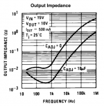
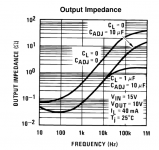
Here are two relevant plots of regulator output impedance. The first is from the regular LM317T (TO220) by way of comparison, the second is the positive regulator used on the Mod-86, the LM317L (TO92).
Worthy of note is that the output impedances of these two differ markedly - the LM317T is at least an order of magnitude lower than the LM317L. The reason for the difference I put down to the difference in the load current - the -T is shown at 500mA and the -L is shown at 40mA. Since the output impedance is presumably a function of the gm of the output transistor, higher gm (from higher load current) gives rise to lower impedance. To me this seems a reasonable deduction to make, if anyone has a reason to doubt the assumption please do share it.
Note also that the relevant curve here for the LM317L is the one with the reference capacitor bypass in place. Also note that the load capacitance for the measurement is 1uF.
Attachments
Last edited:
Paying attention to the curve at 20kHz for the LM317L (right plot) is instructive - this is roughly the point where the 1uF output capacitor takes over the output impedance determination. However my calculator tells me the Xc of 1uF @ 20kHz is about 8ohms so it rather looks as though that measurement was taken with 10uF rather than 1uF for the load capacitance. The curve looks to be cap ESR limited around 2ohms at HF.
Applying a scaling factor of 4 because in the Mod-86 the quiescent load current from the LM317L is about 10mA (vs this plot taken at 40mA) suggests a regulator Zout @ 20kHz around 4ohms. In other words in this application the regulator looks to be entirely irrelevant at 20kHz and above - the capacitors employed are going to determine the Zout.
Applying a scaling factor of 4 because in the Mod-86 the quiescent load current from the LM317L is about 10mA (vs this plot taken at 40mA) suggests a regulator Zout @ 20kHz around 4ohms. In other words in this application the regulator looks to be entirely irrelevant at 20kHz and above - the capacitors employed are going to determine the Zout.
Capacitor ESR considerations
The output caps for the regulators (10uF/50V) are specified as Panasonic EB with a 5*11mm case size. From the Panny DS there's no mention of the ESR so a little investigation is in order.
Cap ESR is inversely related to ripple current in general - the ESR of the cap is the loss within the cap - and rated ripple currents are related to the internal heating of the cap. The specified ripple current rating for the Pana EB in this case size is 27mA, at 120Hz. So I went over to Mouser and looked to see what other caps in this value and case size might have ESR specs.
The first one I found (after sorting on increasing ripple current) was Cornell Dubilier SEK which posts an ESR of 16ohms. But its ripple current rating is higher (50mA vs 27mA). So taking this ratio into account suggests an ESR for the Pana EB of 30ohms. But this is pessimistic at 20kHz because ripple current ratings increase with frequency due to ESRs going down with frequency. The adjustment factor is given in the Pana EB DS - I'll use a factor of 1.6X. So then we end up with an ESR for the LM317L's output capacitor estimated at 18ohms at frequencies above 20kHz. This is a worst case but here I'm doing a worst-case analysis.
I think you are only taking part of my statement. My focus is on association listening experience with technical imperfection. This is a process a refer to as listen, analyse/test, fix. This is an important process whenever designing products that involve human perception. I think distortion is important, but with current technology advancement, there are other much more dominant flaws in the audio reproduction process which masks out the benefits of low distortion in a single equipment.That's complete bogus. THD and IMD are strongly correlated with sound quality, including those you mention. The power response (SPL vs freq vs power) is another indicator that correlates with timbre, sound stage, and the like.
It's pretty clear from Harman Kardon's research that good sound quality and good measurements are correlated. And by "research" I mean actual research. You know... A controlled trial with blind testing and a statistically significant number of test subjects. In some cases over 250 test subjects were used. That's research. What most of us in the DIY world, myself included, do is to get a couple of friends together in a room for a sighted trial while agreeing to not be biased (both by our own preconceived notions and by each other). While that may provide some entertainment, it is rather naive to expect any useful data to come from such an "experiment".
Human perception is incredibly inaccurate and easily affected by many things. If you believe otherwise, I strongly suggest that you open a psychology book and read a bit about human cognition.
SY's article in Linear Audio (available for free here: http://linearaudionet.solide-ict.nl/sites/linearaudio.net/files/LA Vol 2 Yaniger(1).pdf) on audio testing is quite informative. In particular, I enjoyed how he'd subconsciously trained his wife to provide positive feedback whenever he changed something in his audio system.
Also, as I've linked to many times now, Michael Shermer's TED talk on cognitive biases, "Why People Believe in Strange Things", is interesting as well. To skip to the auditory illusion, start the video at 8:00. (13-minute video).
Of course, none of that addresses the fundamental question of, "0.00014 % THD .... That's nice, but can I dance to it?" That depends on your personal preferences. If you expect a certain sonic signature, you'll probably be in for a let-down with the Modulus-86. However, if you expect an acoustically transparent amplifier that just sits back and lets you enjoy the music, you've come to the right place. The Modulus-86 does just that. It is by far the best amplifier I have ever designed - both in terms of measured performance and perceived sound quality (recall, they're correlated...)
Just received word from DHL that the next batch of 100 boards are on their way to my front door.
~Tom
I am sure you also have your views, but my playing around with audio equipment and spending lots of money there since 1980 really had me fed up with all the hype and misunderstanding. This is the reason why I set out to spend time and money in invested in development of a fully integrated solution. I may be traveling to Washington State University in August, if anyone is interested, I should have a small system with me, and would be happy to give people in that area the chance to audition them during my spare time. These are the results of lots of criticism an learning throughout the years. The main thing people appreciate is how much effort is spent to study feedback from audiophiles.
I have an open mind on distortion issues because I have listened to the difference between distortion caused by different layouts. The key issue is humans can learn to link perception with incidences, that is why you may not recognise a voice when you first hear it, but you can distinguish the voices of different people. The same occurs when listening to various issues in audio system reproduction. Testing is very important in the process of ensuring the correlation with listening perception, but is also very dependent on how you measure and the data you look at. At least from my experience. Some people can specifically tell you that one sound is more realistic, but another is preferred. When this happens, it means there is still some problem somewhere. Where it can be found or not really depends on luck sometimes.
Lots of the published research are positioned to prove a point rather than getting into the finer details. I have discovered this when I explored some research of interest much of then usually ignore keeping track of system interface characteristics data, so you really cannot know what else could have contributed to the conclusion. For example, they will compare distortion of machines under constant resistors but not with real speaker loading used in listening tests. Some will increase the distortion differences to levels where they become more dominant to prove a point. Some research will till you that distortion levels below a certain point can be ignored because they cannot be distinguished. But all those publications only tell you the result, lacking the performance data of each equipment used. When you ask them for such data, they will just brush it off saying it is irrelevant. This is sad that people care more about personal status...
The real problem with blind tests is that if you use people whom are not really blind, and they have not spent lots of time tweaking and listening to changes, there listening capability is really not well trained. If you use a naturally blind person, you need to make sure he is well versed in how the real experience sounds. None of the studies I have seen address this. But still, I have found some bits and pieces of information that are of value.
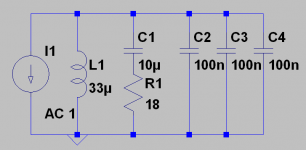
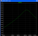
Power supply equivalent circuit
Time to fire up LTSpice for a quick look-see. I've modelled the LM317L as a 33uH inductor (matching the 4ohm Zout at 20kHz) but have no idea what damping it contributes to the circuit. So if anyone has an estimate for that, I'm all ears. I've put in 0.1R series resistance for now.
The vertical scale is in dB but since the current source is 1A, can be interpreted as dB-ohms. The peak at 50kHz at 25dB-ohms corresponds to the ESR I estimated for the 10uF/50V Panasonic EB output capacitor. The remaining 3 caps are 100nF placed at the pins of the three ICs powered by the LM317L. I've assumed their ESR is negligible.
<edit> My earlier post where I figured the output caps were going to determine the impedance above 20kHz looks to be wrong by more than an octave. I hadn't figured that the Pana EB's ESR was going to be as high as it is. So the regulator's inductive output impedance only gets ameliorated above 50kHz with the current decoupling configuration.
Attachments
Last edited:
Soongsc if you're interested in modifying your Mod-86 drop me an email via the forum email facility as I have some suggestions you can try out for yourself. They don't involve boutique components incidentally, they're mods based on engineering considerations.
I'm interested in your "engineering considerations" as well. You've pointed to the finite and non-zero output impedance of the LM317/LM337 regulators. Great. Would you kindly show how this impacts the output signal of the Modulus-86? After all, any supply ripple on the regulated ±15 V supply will be attenuated by the rather stellar PSRR of the LME49710 and THAT1200. Any error voltage induced this way will be further reduced by the loop gain.
I'm curious to see your math and claimed improvement (either calculated, simulated, or measured).
~Tom
After all, any supply ripple on the regulated ±15 V supply will be attenuated by the rather stellar PSRR of the LME49710 and THAT1200.
How stellar is the PSRR of the THAT1200? I saw no graphs when looking at the DS, so perhaps you can enlighten us all? I did see one quoted number, but no frequency attached to that.
Let's just for argument's sake assume 0 dB PSRR in the THAT1200. What does your math say the contribution from the finite output impedance of the LM317/LM337 will be in that case?
If you want to get an estimate for the 20 kHz PSRR of the THAT1200, you could extrapolate from the 60 Hz number given in the data sheet assuming a 20 dB/dec slope. What does your math say in that case?
~Tom
If you want to get an estimate for the 20 kHz PSRR of the THAT1200, you could extrapolate from the 60 Hz number given in the data sheet assuming a 20 dB/dec slope. What does your math say in that case?
~Tom
Last edited:
The LME49710 is seeing a load of 1.33kohms. It seems to me this is going to be the major source of load-induced noise on the rails. Working back from the LM3886 output it seems there's going to be a peak voltage at the output of the LME49710 of about 13V hence a peak current demand of 10mA. Note the peak current demand is not the audio signal itself, rather a half-wave rectified version of the audio signal.
<edit> A quick and dirty non-linear LTSpice simulation shows about 100mV peak to peak on the supplies from a 20kHz full scale sinewave applied to a classAB output stage driving 10mA peak current (1330 ohm load). With your 0dB PSRR that'll go straight to the output of your THAT1200.
<edit> A quick and dirty non-linear LTSpice simulation shows about 100mV peak to peak on the supplies from a 20kHz full scale sinewave applied to a classAB output stage driving 10mA peak current (1330 ohm load). With your 0dB PSRR that'll go straight to the output of your THAT1200.
Last edited:
Correct so far.
You can find the output impedance for the LM337T in the data sheet from National Semiconductor (available here). The output impedance is about 10 mΩ at 20 kHz (note: data sheet shows the curve for Cadj = 10 µF, I use Cadj = 22 µF), so the 10 mA load current pulses at 20 kHz (worst case) results in 100 µV of ripple on the ±15 V supply.
Assuming a 20 dB/dec slope from the 80 dB (60 Hz) PSRR of the THAT1200, the PSRR at 20 kHz is: 80-log(20000/60)*20 = 29.5 dB. 100 µV attenuated by 29.5 dB is 3.33 µV. So the load current induced ripple on the LM337 supply at 20 kHz results in an error voltage at the output of the THAT1200 of 3.33 µV.
The 3.33 µV error voltage gets amplified by the full gain of the Modulus-86, resulting in an error on the output of the Modulus-86 of 33.3 µV. The desired signal, meanwhile, will be at an amplitude of 35.5 V. 20*log(33.3E-6/35.5) = -141 dB.
CONCLUSION: The finite output impedance of the LM337T results in an error voltage that is 141 dB down from the desired signal; 6 dB below the noise floor of the amplifier.
Math. Engineering. Useful... What was the issue again?
~Tom
Last edited:
You can find the output impedance for the LM337T in the data sheet from National Semiconductor (available here). The output impedance is about 10 mΩ at 20 kHz (note: data sheet shows the curve for Cadj = 10 µF, I use Cadj = 22 µF), so the 10 mA load current pulses at 20 kHz (worst case) results in 100 µV of ripple on the ±15 V supply.
Turns out the Zout for the LM317L is worse than for the LM337T. Of course you're free to cherry pick (substituting LM337T for LM337L) but here I'm doing conservative engineering. You also make the error of taking the Zout at 500mA output current, so re-do the math for 10mA.
Quick-and-dirty LTSpice sim output attached. Its a bit pessimistic because presumably by the time the regulator's output current has increased to 20mA the Zout will be halved. But it gets us in the ballpark.
Attachments
Last edited:
Turns out the Zout for the LM317L is worse than for the LM337T.
Earlier you said otherwise.
Of course you're free to cherry pick (substituting LM337T for LM337L)
And there go the accusations. I went with the data you provided.
You also make the error of taking the Zout at 500mA output current, so re-do the math for 10mA.
That's very interesting. The load current alone is 10 mA. The OPA277 uses 0.8 mA. The LME49710, 4.8 mA. And the THAT1200, 4.7 mA. So shouldn't the output impedance be characterized at 20.3 mA?
Quick-and-dirty LTSpice sim output attached. Its a bit pessimistic because presumably by the time the regulator's output current has increased to 20mA the Zout will be halved. But it gets us in the ballpark.
Your simulation shows the LM317 having an output impedance of 5 Ω. Would you care to show how you arrived at that number. Attached figure from the National Semiconductor LM317L data sheet shows about 1 Ω output impedance.
I still haven't seen any numbers from you that indicate the amount of error voltage present on the output of the Modulus-86 resulting from this finite non-zero output impedance of the LM317/LM337. I've shown you my math. Would you please show yours?
If there was an issue, it would have shown up in the measurements. On the Modulus-86 Rev. 2.0, I measure 0.00014 % THD.
~Tom
Attachments

Last edited:
Earlier you said otherwise.
Where? Happy to be corrected.
And there go the accusations.
How strange you see accusations whereas I just observe behaviour and report back on what I see.
That's very interesting. The load current alone is 10 mA. The OPA277 uses 0.8 mA. The LME49710, 4.8 mA. And the THAT1200, 4.7 mA. So shouldn't the output impedance be characterized at 20.3 mA?
No because the load current is transient, I go with the quiescent. I already pointed out that the sim was rather pessimistic due to this effect.
Your simulation shows the LM317 having an output impedance of 5 Ω. Would you care to show how you arrived at that number. Attached figure from the National Semiconductor LM317L data sheet shows about 1 Ω output impedance.
Already explained how I did that further up the thread. I'm not going to restate it just because you didn't read it. If you disagree with my reasoning, please shout.
I still haven't seen any numbers from you that indicate the amount of error voltage present on the output of the Modulus-86 resulting from this finite non-zero output impedance of the LM317/LM337.
The sim I just posted shows the effect of the 10mA haversine current on the equivalent circuit I already posted up. That is showing 100mV peak to peak which I accept is perhaps pessimistic by up to 6dB. Going with the sim for now gives 50mV peak on the supply of your THAT1200. What does your PSRR estimate suggest now for what happens at the THAT1200 output?
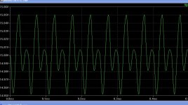
At the full rated output power (38 W into 8 Ω*on ±28 V rails) at 20 kHz, I measure 3.0 mV RMS on the -15 V supply and 4.0 mV RMS on the +15 V supply. This measured using a true RMS bench top voltmeter with 800 kHz bandwidth.
Looking at the waveform on an oscilloscope, it looks nothing like your simulation. It looks more like a sine wave with a frequency of 20 kHz. Before you draw conclusions based on your simulation model, I suggest you correlate it with reality...
~Tom
Looking at the waveform on an oscilloscope, it looks nothing like your simulation. It looks more like a sine wave with a frequency of 20 kHz. Before you draw conclusions based on your simulation model, I suggest you correlate it with reality...
~Tom
- Home
- Amplifiers
- Chip Amps
- Modulus-86 build thread