I read remark about 16 ohm Faital having more treble. In Spice it isn't much difference compared to 4 ohm unit, 1dB more for 16 ohm unit above 10k, but my model might not be very real 🙂 9 ohm resistor with the 4 ohm unit and you might see less difference between the responses of both Faitals. The MA roll off isn't suppose to be there?? I haven't looked at that unit except here, around 700hz there is something, but others show something there too,less, but I don't see that in their own responscurves, Faital and Peerless/Vifa I did look at, the paper RS looks like I would like that one.
spice/sim for 10uH/680nF/3.3/10nF outputfilter I mean above
spice/sim for 10uH/680nF/3.3/10nF outputfilter I mean above
Last edited:
I am seeing that the 16ohm Faital is perhaps one of the better drivers in this lineup, after the TC9FD. Adding a resistor is interesting but will increase the Qts quite a bit. I am going to have to build a Karlsonator for the. 3FE22 16ohm to use. Add the K aperture and the polar data will be greatly extended and smoothed out.
X, could you revise the plots for the CHN-70 and RS100P-4 to 5 dB imcrements as well, even as that means some info falls off of the plot scale?
I had to remind myself it is a 10 dB scale because the off axis response seemed to trace on axis better on these two (after equalisation on axis it would seem superior) based on the plot as posted.
As presented, even with the side note both look like they behave better than they actually are.
I had to remind myself it is a 10 dB scale because the off axis response seemed to trace on axis better on these two (after equalisation on axis it would seem superior) based on the plot as posted.
As presented, even with the side note both look like they behave better than they actually are.
I think the CHN-70 does indeed have a more consistent polar response, although it achieves this by having little to no output in the 14kHz to 20kHz range so beaming is not as much of an issue. But pehaps as you say, equalizing it will boost the HF's uniformly across the angular spread. I am working on getting the 5dB plots. I had to transfer the native REW files onto a bigger laptop with larger screen to produce larger plots. While I am at it, I want to make some spectral decay contour plots (spectrograms) but unsure of what parameters to use for the window gating to produce the data. Maybe 10ms window and 4ms gate consistent with the other data?
Regarding on axis data think bit like xrk971 ordered to wash a car 3-5 times even it was clean first time 🙂, good enough as diy data the first time thanks x making quite lot of work to stay objective.
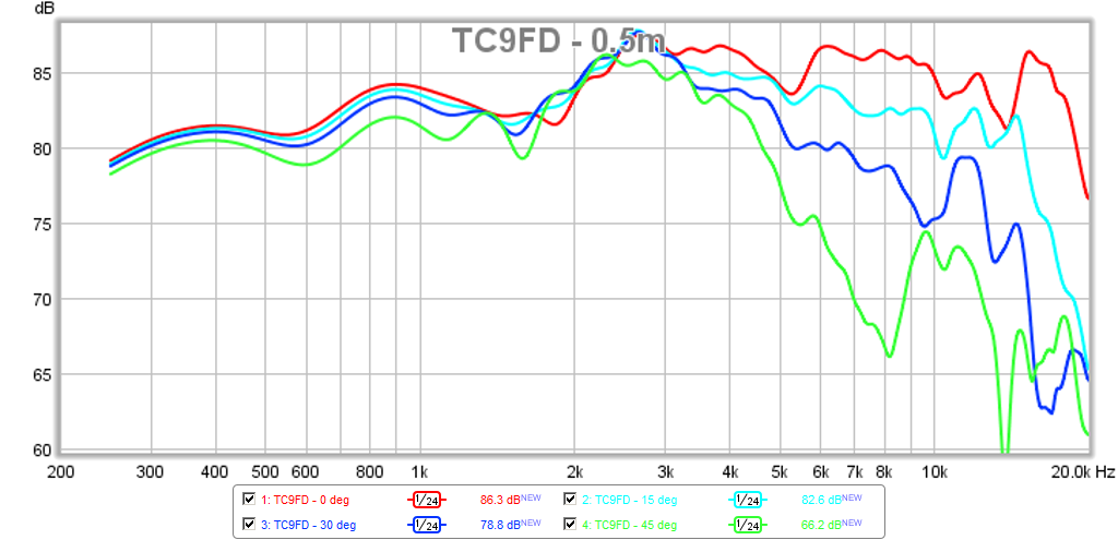
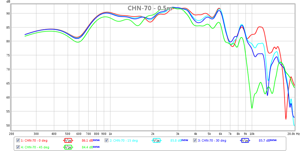
Polar data at 0.5m at 5dB/div with 4ms gate
I am re-posting the plots for the RS100P-4 and CHN-70 at 5dB/div vertical scale as requested by several members. I will include the previous plots for easy comparison.
TC9FD:
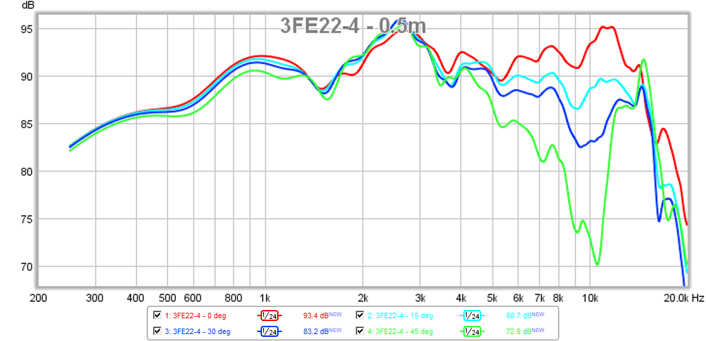
3FE22-4:
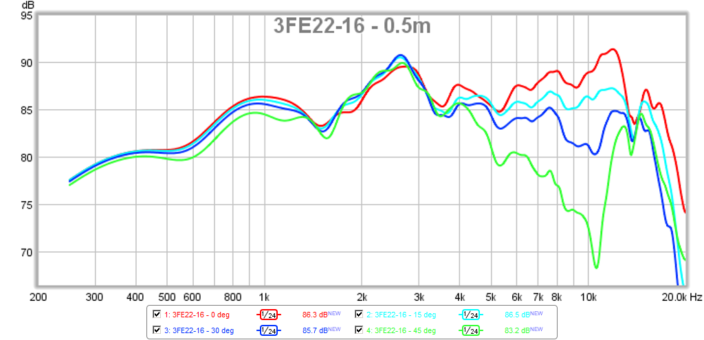
3FE22-16:
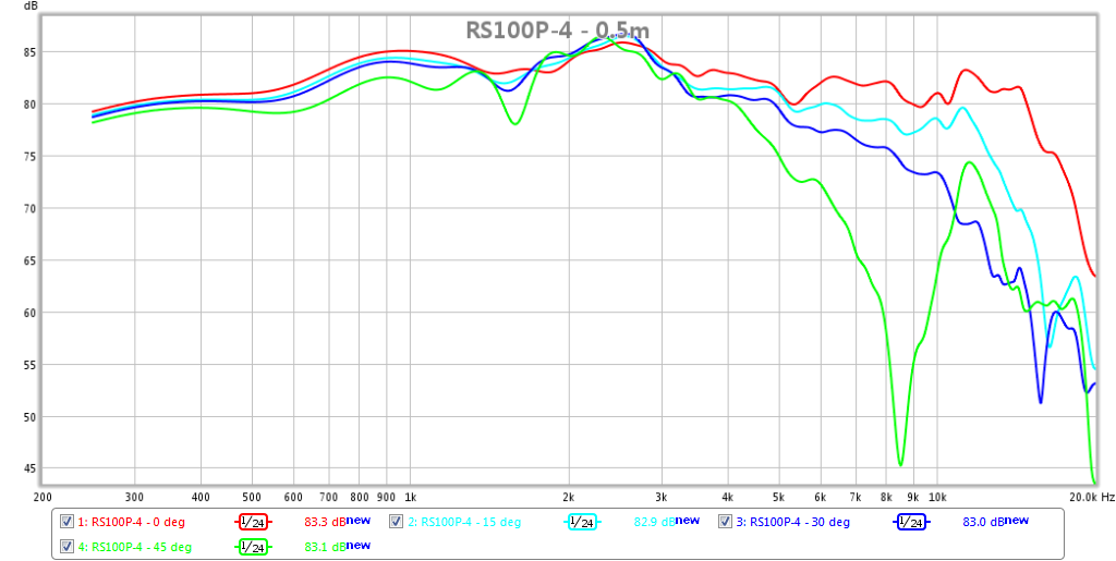
RS100-4:

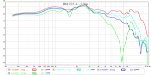
RS100P-4 (revised 5dB/div):
CHN-70 (revised 5dB/div):
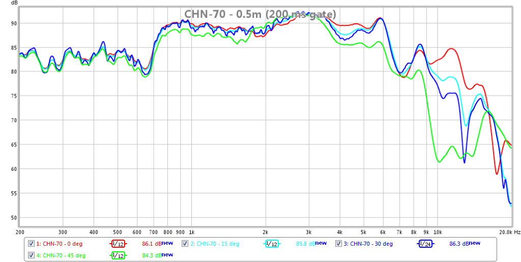
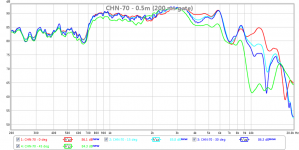
For comparison, this is what the 0.5m data looks like with a 200ms gate - still the same general response but there are some small wiggles due to reflections causing combing effects in the lower frequency range. Note that the upper frequency range and the rapid HF fall off is independent of gating. That is, gating should not be blamed for a response in the HF that doesn't match expected performance. Also note that the longer gate allows a higher frequency resolving plot that shows, more accurately, just how steep the cliffs are on the 700Hz to 7kHz plateau is - as Byrtt mentioned previously, this steep wall will wreak havoc on phase and group delay:
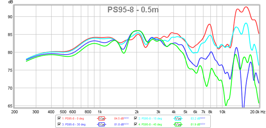
PS95-8:
I am re-posting the plots for the RS100P-4 and CHN-70 at 5dB/div vertical scale as requested by several members. I will include the previous plots for easy comparison.
TC9FD:
3FE22-4:
3FE22-16:
RS100-4:
RS100P-4 (revised 5dB/div):
CHN-70 (revised 5dB/div):
For comparison, this is what the 0.5m data looks like with a 200ms gate - still the same general response but there are some small wiggles due to reflections causing combing effects in the lower frequency range. Note that the upper frequency range and the rapid HF fall off is independent of gating. That is, gating should not be blamed for a response in the HF that doesn't match expected performance. Also note that the longer gate allows a higher frequency resolving plot that shows, more accurately, just how steep the cliffs are on the 700Hz to 7kHz plateau is - as Byrtt mentioned previously, this steep wall will wreak havoc on phase and group delay:
PS95-8:
Attachments

Last edited:
I am seeing that the 16ohm Faital is perhaps one of the better drivers in this lineup, after the TC9FD. Adding a resistor is interesting but will increase the Qts quite a bit. I am going to have to build a Karlsonator for the. 3FE22 16ohm to use. Add the K aperture and the polar data will be greatly extended and smoothed out.
🙂 just Re and Le in sim. But listening to earlier MA paper unit difference heard seems bigger than simulated difference, maybe components in sim are too perfect or.. well don't know.
Thanks again X for the off-axis measurements. The new 4ms gated measurements look very good indeed. There is no doubt that these measurements quantify differences between the drivers under comparison.
Looking at the Vifa measurements, it is flatter and the response is even in a 60 degree window. Looking at the more even CHN70 measurements, it looks like the the highs are more even, but the response is quite ragged. IMO, the 700 Hz blip on the CHN70 is where the cone decouples and hands over to the center element, kind of like a whizzer cone. I have seen traditional whizzer cone designs where the handover happens at > 2 kHz, so this is something new. Wonder if the other MA drivers work this way. The impedance graph on the other drivers should show where the handoff happens.
Looking at the Vifa measurements, it is flatter and the response is even in a 60 degree window. Looking at the more even CHN70 measurements, it looks like the the highs are more even, but the response is quite ragged. IMO, the 700 Hz blip on the CHN70 is where the cone decouples and hands over to the center element, kind of like a whizzer cone. I have seen traditional whizzer cone designs where the handover happens at > 2 kHz, so this is something new. Wonder if the other MA drivers work this way. The impedance graph on the other drivers should show where the handoff happens.
Thanks again X for the off-axis measurements. The new 4ms gated measurements look very good indeed. There is no doubt that these measurements quantify differences between the drivers under comparison.
Looking at the Vifa measurements, it is flatter and the response is even in a 60 degree window. Looking at the more even CHN70 measurements, it looks like the the highs are more even, but the response is quite ragged. IMO, the 700 Hz blip on the CHN70 is where the cone decouples and hands over to the center element, kind of like a whizzer cone. I have seen traditional whizzer cone designs where the handover happens at > 2 kHz, so this is something new. Wonder if the other MA drivers work this way. The impedance graph on the other drivers should show where the handoff happens.
Ra7,
Thanks, I think the data looks pretty good too - not sure if it will make the "Believers" change their views though. I can take impedance sweeps of all the drivers as that is an easy test, but I have yet to see another 3in or 4in whizzercone-less driver have a big impedance blip like that. At 700Hz that is way too low to say it is where the driver transitions from pistonic to cone break up mode for HF's. That generally is around 6 to 8kHz for this size driver.
Last edited:
Not saying it transitions to cone breakup, but that it transitions to the center element in the driver, the thing in place of the dustcap. Some other larger drivers, like the FE206 have a central whizzer element and the large cone sort of rolls of and the whizzer radiates the high frequencies. It's like a mechanical crossover. I'm saying the MA drivers could be designed such that this handoff happens at a much lower frequency, where the impedance blip lies. Just saying it may be one reason why the response off-axis follows the the on-axis even above 5 kHz, because a smaller element is radiating.
🙂 just Re and Le in sim. But listening to earlier MA paper unit difference heard seems bigger than simulated difference, maybe components in sim are too perfect or.. well don't know.
My MA is metal 10.2 and at listening (subjective) it goes wrong when adding R this driver and have a guess it's the softer elastic you add at electric dampning that degrade it because this one likes resonance (RLC) and inductance (RC) compensation filters which raise sound quality and tighten the electric elastic.
Not saying it transitions to cone breakup, but that it transitions to the center element in the driver, the thing in place of the dustcap. Some other larger drivers, like the FE206 have a central whizzer element and the large cone sort of rolls of and the whizzer radiates the high frequencies. It's like a mechanical crossover. I'm saying the MA drivers could be designed such that this handoff happens at a much lower frequency, where the impedance blip lies. Just saying it may be one reason why the response off-axis follows the the on-axis even above 5 kHz, because a smaller element is radiating.
Actually, I suggested the same thing earlier in this thread but told by the Expert that it is otherwise, and related to the pistonic transition:
http://www.diyaudio.com/forums/full-range/270094-objective-comparison-3in-4in-class-full-range-drivers-2.html#post4231325
But as it is occuring at 700Hz, I would have to agree with you and assume this is more related to the mechanical XO going on from the cone to the button shaped dustcap.
Last edited:
That looks much better. Thanks for doing it. The Faital Pro makes me interested for a mid in a 3 way.
Only last thing I would recommend, is stating the limitations of the test clearly as you've seen people can misunderstand easily. In this case it would be the test is not useful below 1/0.004 hz and not very detailed below 2.5/0.004 hz. Also mention any smoothing, polar angles, etc. That sort of thing helps people view the data in a more concentrated fashion. I've been there. I once tested the alp 6 and FF85wkEn together and posted here. They were in different boxes and even though I alluded to that, some people lost their mind because of this. They didn't understand it was expected of the viewer to judge the data based on the box sizes I had them in. It was my lack of explanation and their lack of knowledge that lead to quite a frustrating conversation. 😱
Only last thing I would recommend, is stating the limitations of the test clearly as you've seen people can misunderstand easily. In this case it would be the test is not useful below 1/0.004 hz and not very detailed below 2.5/0.004 hz. Also mention any smoothing, polar angles, etc. That sort of thing helps people view the data in a more concentrated fashion. I've been there. I once tested the alp 6 and FF85wkEn together and posted here. They were in different boxes and even though I alluded to that, some people lost their mind because of this. They didn't understand it was expected of the viewer to judge the data based on the box sizes I had them in. It was my lack of explanation and their lack of knowledge that lead to quite a frustrating conversation. 😱
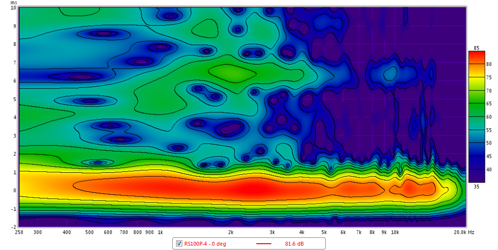
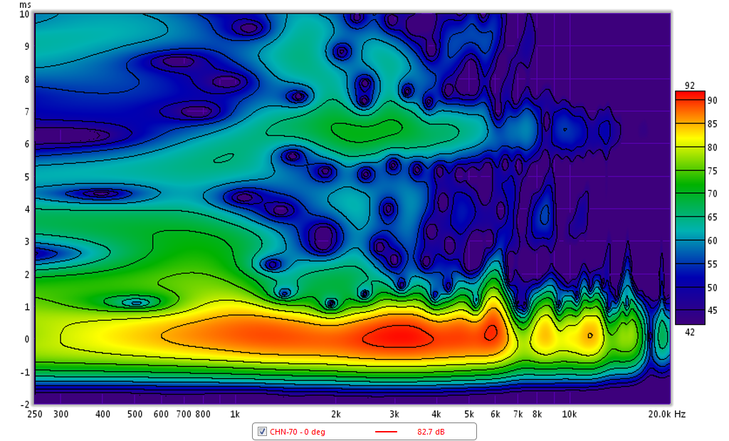
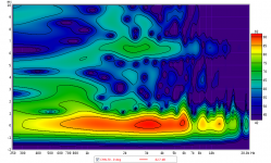
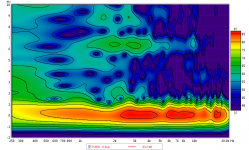
Temporal Decay via Spectrograms
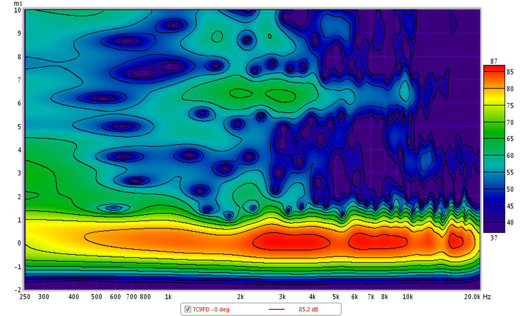
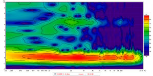
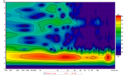
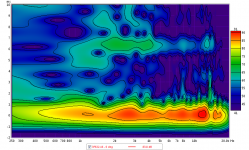
Here are some spectrograms calculated by REW - I used a 4ms gate and 10ms window setting. If anyone knows or thinks there may be a better setting for the calculation, let me know. I think this is useful for seeing the decaying tendrils of resonance peaks - any vertical persistance is ringing in the time domain. These are all for 0 deg on axis measurement at 0.5m with drive level set at -10dB below 2.83v (same as previous set of plots). I think that everything beyond the 4ms gate is a reflection from some hard object or boundary nearby, and under 4ms though, that is the real (intrinsic) decay of the driver - I think same as the CSD but in a color contour plot.
TC9FD:
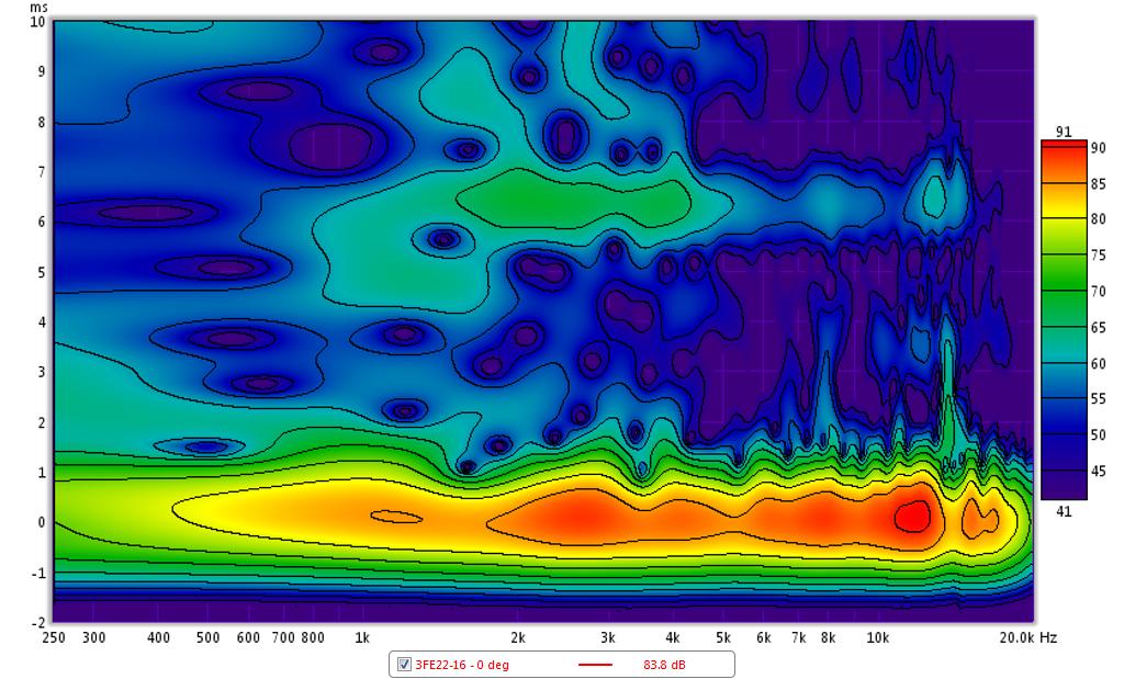
3FE22-16:
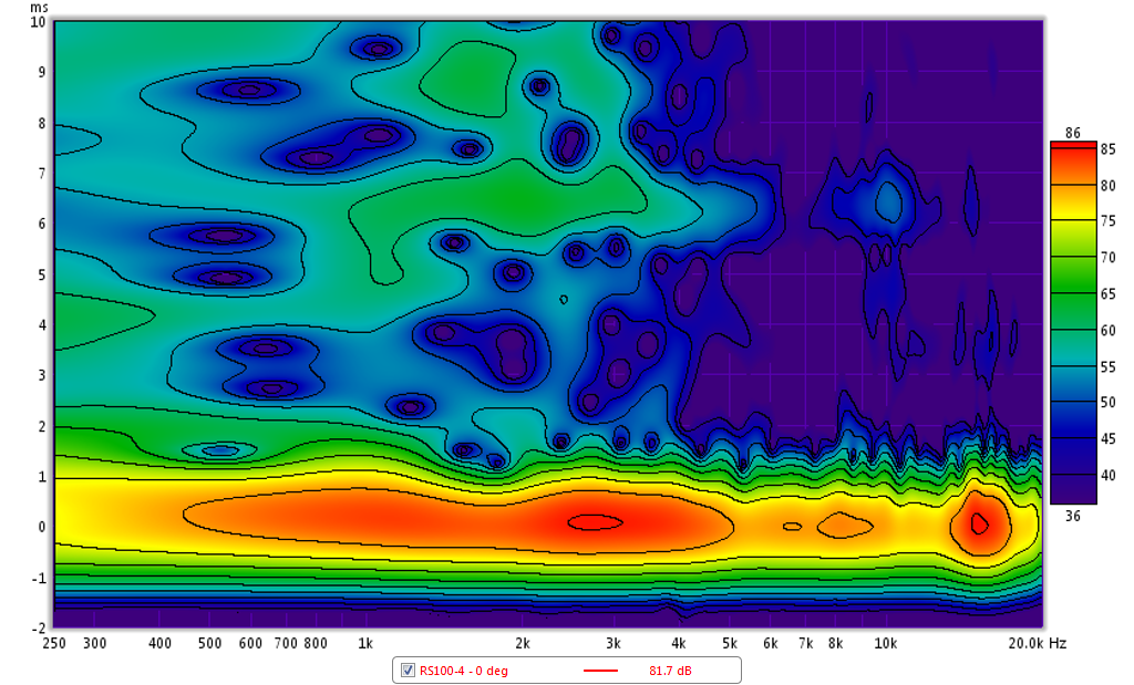
RS100-4:
RS100P-4:
CHN-70:
PS95-8:
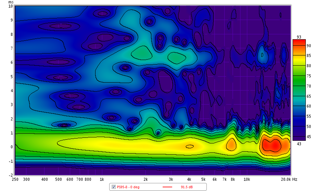
Here are some spectrograms calculated by REW - I used a 4ms gate and 10ms window setting. If anyone knows or thinks there may be a better setting for the calculation, let me know. I think this is useful for seeing the decaying tendrils of resonance peaks - any vertical persistance is ringing in the time domain. These are all for 0 deg on axis measurement at 0.5m with drive level set at -10dB below 2.83v (same as previous set of plots). I think that everything beyond the 4ms gate is a reflection from some hard object or boundary nearby, and under 4ms though, that is the real (intrinsic) decay of the driver - I think same as the CSD but in a color contour plot.
TC9FD:
3FE22-16:
RS100-4:
RS100P-4:
CHN-70:
PS95-8:
Attachments
Last edited:
That looks much better. Thanks for doing it. The Faital Pro makes me interested for a mid in a 3 way.
Only last thing I would recommend, is stating the limitations of the test clearly as you've seen people can misunderstand easily. In this case it would be the test is not useful below 1/0.004 hz and not very detailed below 2.5/0.004 hz. Also mention any smoothing, polar angles, etc. That sort of thing helps people view the data in a more concentrated fashion. I've been there. I once tested the alp 6 and FF85wkEn together and posted here. They were in different boxes and even though I alluded to that, some people lost their mind because of this. They didn't understand it was expected of the viewer to judge the data based on the box sizes I had them in. It was my lack of explanation and their lack of knowledge that lead to quite a frustrating conversation. 😱
Good points. I will be sure to add limitations of data presented in future plots. Maybe embed right into title provided by REW.
TC9FD:
CHN-70 (revised 5dB/div):
Looks like CHN70 has much better off-axis performance than Vifa.
Too bad the on-axis is what it is. The one who is 60+ starts to like CHN70 😀
Actually the very wide angle radiation up to 6kHz can sound very good in a room. Spacious. No beaming.
If I were to make a three way and crossing at 800 and 6kHz, CHN70 could be one option as a midrange.
In the past I had some Mark Audio drivers, and I absolutely hated their whimpy plastic frames, but I'm delighted they are going to metal frame now.
CHN70 is not available in Europe ? Why not ?

.
It should be -I think Oak Audio will be carrying them. However, that does bring us on to a little point which has been, inadvertently I'm sure, overlooked thus far:
The CHN70 was not designed to have a flat response. MA's Japanese distributor requested an entry level driver with a specific set of features, and the CHN was the result. The desired characteristics were for a nominal 4in driver with a surface-mount basket of similar type & dimensions to that of the Fostex 103, but with a different FR trend / tonal balance. The 103 is very popular in Japan, but is quite hot at the top end, and there was also demand for a unit with the opposite: lots of linear travel for the LF, and a gently rolled off HF. As I understand it, it wasn't expected to be sold outside of Japan. However, there was interest, so it was released on a wider scale. None of this is news, or secret: it was all set out during its development. So if people are moaning that it doesn't have a flat response, a die-cast basket etc., then their complaints are, alas, based on somewhat flawed reasoning since it wasn't supposed to in the first place. In the meantime, I have zero wish, nor interest, in becoming embroiled in an acrimonious debate so this will be my only post on this thread.
The CHN70 was not designed to have a flat response. MA's Japanese distributor requested an entry level driver with a specific set of features, and the CHN was the result. The desired characteristics were for a nominal 4in driver with a surface-mount basket of similar type & dimensions to that of the Fostex 103, but with a different FR trend / tonal balance. The 103 is very popular in Japan, but is quite hot at the top end, and there was also demand for a unit with the opposite: lots of linear travel for the LF, and a gently rolled off HF. As I understand it, it wasn't expected to be sold outside of Japan. However, there was interest, so it was released on a wider scale. None of this is news, or secret: it was all set out during its development. So if people are moaning that it doesn't have a flat response, a die-cast basket etc., then their complaints are, alas, based on somewhat flawed reasoning since it wasn't supposed to in the first place. In the meantime, I have zero wish, nor interest, in becoming embroiled in an acrimonious debate so this will be my only post on this thread.
Last edited:
Too bad the on-axis is what it is. The one who is 60+ starts to like CHN70 😀
.
.
.
If I were to make a three way and crossing at 800 and 6kHz, CHN70 could be one option as a midrange.
Yeah, the off-axis follows the on-axis, but on-axis is terrible, so terrible in fact that you probably cannot EQ it either. It's up/down, peaks and valleys, all over the place.
With aging comes hearing loss, usually in the HF. But still, you can make it up by boosting the HF. Unless your hearing loss follows the same curve as the CHN70 and in the same proportion, an HF boost could work better.
Regarding your comment on using it as a midrange, you should check out the first post in this thread and XRK's analysis on the distortion around 700 Hz. It could be made to work with some EQ, but there are better more cheaper options out there.
Last edited:
Wonder if the other MA drivers work this way.
Yes, althou the transition frequency may be a bit different.
Actually one can say that all FRs work like this more or less.Often one will see a train of smaller impedance peaks as there are a number of transition points.
Attached an Audio Nirvana Super 10.
dave
Attachments
- Status
- Not open for further replies.
- Home
- Loudspeakers
- Full Range
- An Objective Comparison of 3in - 4in Class Full Range Drivers