Hi,
has anyone connected this DAC differential outputs to Broskie Cathode Follower of The Unbalancer ?
Any pointers ?
has anyone connected this DAC differential outputs to Broskie Cathode Follower of The Unbalancer ?
Any pointers ?
To be precise, where do I find GND pins to use with +DACR- and +DACL- outputs ?
Mine using the gnd. point of +12,0,-12 VDC....say = 0 V point = gnd pin (1) of the XLR out put.
cheer
I have been trying hard to track down more information about SPDIF connections of this board, but to no avail. So I ask my question here.
According to hifiduino the es9108k2m offers two SPDIF inputs. But the board only seems to offer one SPDIF connection: image and description by hifiduino (middle of the page)
Could someone (diyinhk?) please confirm, if a second SPDIF input is possible with this board and if yes - how/where to connect it?
Hi all,
could someone clarify the difference between the two different options here
ES9018K2M XMOS DSD DXD 384kHz USB DAC with Bit-perfect volume control and SPDIF input - DIYINHK
- XMOS, DAC and led PCB (140$)
- isolated XMOS, DAC and led PCB (170$)
I do not understand the difference...
More: is the short flat cable in the kit or do I need one?
Hi all,
could someone clarify the difference between the two different options here
ES9018K2M XMOS DSD DXD 384kHz USB DAC with Bit-perfect volume control and SPDIF input - DIYINHK
- XMOS, DAC and led PCB (140$)
- isolated XMOS, DAC and led PCB (170$)
I do not understand the difference...
More: is the short flat cable in the kit or do I need one?
The $170 package has a different XMOS adaptor (with gravanic isolator ICs).
Isolated XMOS DSD DXD 384kHz high-quality USB to I2S/DSD PCB with ultralow noise regulator - DIYINHK
The $170 package has a different XMOS adaptor (with gravanic isolator ICs).
Isolated XMOS DSD DXD 384kHz high-quality USB to I2S/DSD PCB with ultralow noise regulator - DIYINHK
I see, thanks!
Do you think improvement in sound quality would Be very noticeable, in your opinion?
More: do you think I Can use this little transformer for feeding the 2 rectifier/regulators for 3.3V and 5V?
An externally hosted image should be here but it was not working when we last tested it.
No at all
you need
one transformer 2X9V 40VA total AC for 3,3 analog 3,3 digital
one transormer 2X15V AC 40VA total for opamp
and one 1x9 or 1X12 40VA for USB card 3,3V 5V (Amanero .....etc)
OR ONE FOR ALL
you need
one transformer 2X9V 40VA total AC for 3,3 analog 3,3 digital
one transormer 2X15V AC 40VA total for opamp
and one 1x9 or 1X12 40VA for USB card 3,3V 5V (Amanero .....etc)
OR ONE FOR ALL
No at all
you need
one transformer 2X9V 40VA total AC for 3,3 analog 3,3 digital
one transormer 2X15V AC 40VA total for opamp
and one 1x9 or 1X12 40VA for USB card 3,3V 5V (Amanero .....etc)
OR ONE FOR ALL
I think you miss something: there are only 3 psu sockets to be fed, not 5.
+-12V
3.3V
5V
Hi Kooka
I say 4 psu not 5
((and one 1x9 or 1X12 40VA for USB card 3,3V 5V (Amanero .....etc ))
5 volts for outside for Amanero or 3,3 for Amanero if pull out the LDO 3,3V from board .
ONE 3,3 for analog and ONE 3,3 for digital for Dac if you want two separate PSU, the job can be done with one but its not the same .
and one +/- for opamp.
Last edited:
Hi Kooka
I say 4 psu not 5
((and one 1x9 or 1X12 40VA for USB card 3,3V 5V (Amanero .....etc ))
5 volts for outside for Amanero or 3,3 for Amanero if pull out the LDO 3,3V from board .
ONE 3,3 for analog and ONE 3,3 for digital for Dac if you want two separate PSU, the job can be done with one but its not the same .
and one +/- for opamp.
Hi Nico, thanks, got what you mean.
Simultaneous USB and Toslink input
Hi
I am very tempted to order the full DAC (DAC, USB receiver and power supplies) but I also need to be certain if I can connect simultaneously the USB receiver and a Toslink input.
On the DIYINHK website is stated that the input labeled "SPDIF IN" can be used to directly connect a SPDIF optical receiver(Toshiba TORX147 or equivalent).
However the pictures published on the DIYINHK-website are not clear in this regard. I think the picture of the backside of the board does not conform with the picture of the upside, and I also cannot see how the Toslink could be directly connected to the DAC-board.
I send DIYINHK a mail raising the exact same question.
When I receive a clearcut answer, I will certainly post again.
Did you in the meantime found the answer?
Joris
I have been trying hard to track down more information about SPDIF connections of this board, but to no avail. So I ask my question here.
According to hifiduino the es9108k2m offers two SPDIF inputs. But the board only seems to offer one SPDIF connection: image and description by hifiduino (middle of the page)
Could someone (diyinhk?) please confirm, if a second SPDIF input is possible with this board and if yes - how/where to connect it?
Hi
I am very tempted to order the full DAC (DAC, USB receiver and power supplies) but I also need to be certain if I can connect simultaneously the USB receiver and a Toslink input.
On the DIYINHK website is stated that the input labeled "SPDIF IN" can be used to directly connect a SPDIF optical receiver(Toshiba TORX147 or equivalent).
However the pictures published on the DIYINHK-website are not clear in this regard. I think the picture of the backside of the board does not conform with the picture of the upside, and I also cannot see how the Toslink could be directly connected to the DAC-board.
I send DIYINHK a mail raising the exact same question.
When I receive a clearcut answer, I will certainly post again.
Did you in the meantime found the answer?
Joris
Simultaneous USB and Toslink input
Hi
I received good and clearcut answers from DIYINHK. I must say from my first contacts with them that their support and service look very good.
From their information I deduce the following.
You should look at the 4th image of the DAC-board product description on the DIYINHK-website.
The SPDIF-IN has two connection holes. The round one is for the output signal and the square one is for ground. For optical input one should use a Toslink input connection TORX147. The TORX147 has an output pin, a ground pin and a 3,3V supply pin. According to the torx147 official datasheet, a 0.1 uf decoupling cap is needed on the torx147 3.3v supply pin and the ground pin.
By default the board works with I2S. But if you make a connection between the two pin-holes SPDIF-ON it will switch from I2S to SPDIF. You can install a jumper on the board to switch between I2S and SPDIF, or you can make from the SPDIF-ON connections onwards a switch on your DAC case to switch between I2S and SPDIF.
Therefore the DAC-board can receive an optical input directly and be connected with USB through a receiver. If one wants to use the Toslink/SPDIF, one will have to switch from I2S to SPDIF.
I hope this might be helpful.
Hi
I am very tempted to order the full DAC (DAC, USB receiver and power supplies) but I also need to be certain if I can connect simultaneously the USB receiver and a Toslink input.
On the DIYINHK website is stated that the input labeled "SPDIF IN" can be used to directly connect a SPDIF optical receiver(Toshiba TORX147 or equivalent).
However the pictures published on the DIYINHK-website are not clear in this regard. I think the picture of the backside of the board does not conform with the picture of the upside, and I also cannot see how the Toslink could be directly connected to the DAC-board.
I send DIYINHK a mail raising the exact same question.
When I receive a clearcut answer, I will certainly post again.
Did you in the meantime found the answer?
Joris
Hi
I received good and clearcut answers from DIYINHK. I must say from my first contacts with them that their support and service look very good.
From their information I deduce the following.
You should look at the 4th image of the DAC-board product description on the DIYINHK-website.
The SPDIF-IN has two connection holes. The round one is for the output signal and the square one is for ground. For optical input one should use a Toslink input connection TORX147. The TORX147 has an output pin, a ground pin and a 3,3V supply pin. According to the torx147 official datasheet, a 0.1 uf decoupling cap is needed on the torx147 3.3v supply pin and the ground pin.
By default the board works with I2S. But if you make a connection between the two pin-holes SPDIF-ON it will switch from I2S to SPDIF. You can install a jumper on the board to switch between I2S and SPDIF, or you can make from the SPDIF-ON connections onwards a switch on your DAC case to switch between I2S and SPDIF.
Therefore the DAC-board can receive an optical input directly and be connected with USB through a receiver. If one wants to use the Toslink/SPDIF, one will have to switch from I2S to SPDIF.
I hope this might be helpful.
Has anyone gotten this pcb working?Incase what spdif 2 TTL converter did you use?
I built the third one (with SN75176) on the photo:
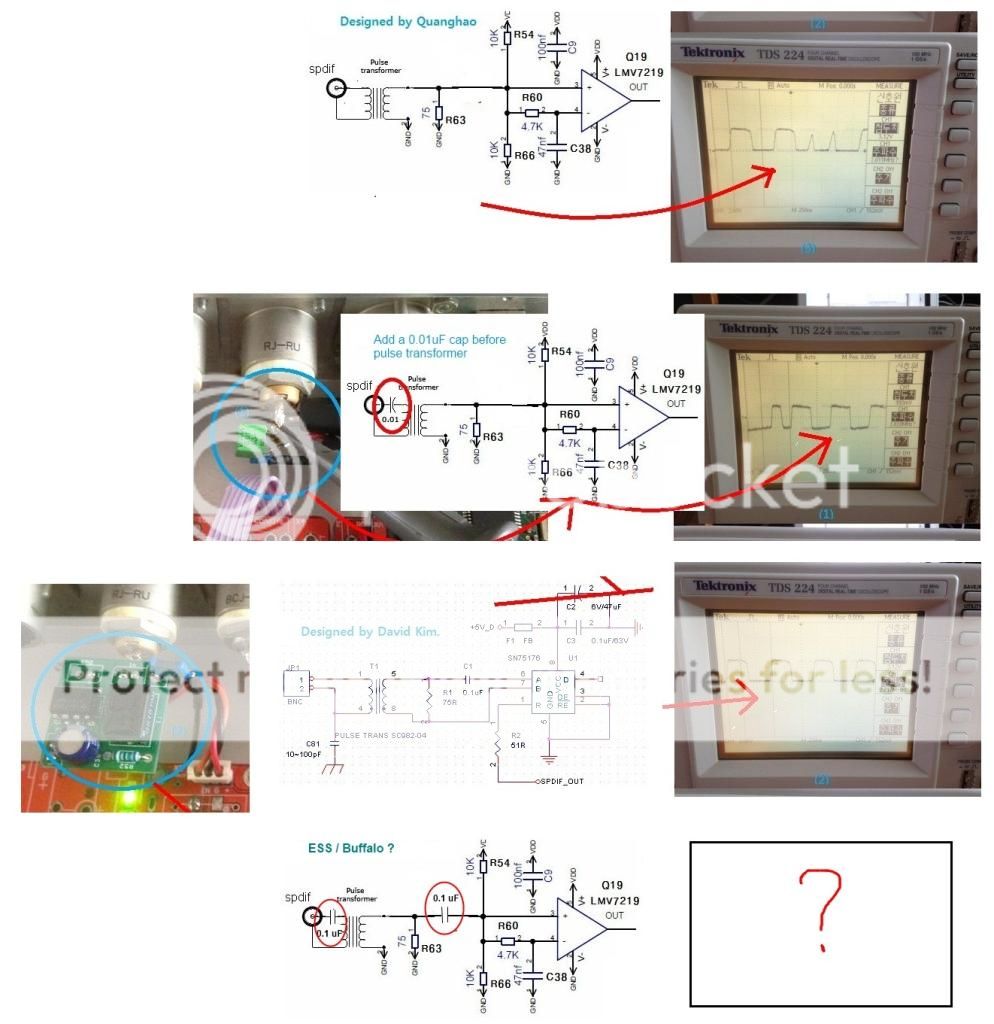
But it seems to oschillate,the speakercone slowly goes back and forward and no sound...on the scope I get a signal of about 4v.
I built the third one (with SN75176) on the photo:
But it seems to oschillate,the speakercone slowly goes back and forward and no sound...on the scope I get a signal of about 4v.
I got read of the "oschillation by placing a cap in series with the spdif out.
But still no music..
But still no music..
Last edited:
HiMine using the gnd. point of +12,0,-12 VDC....say = 0 V point = gnd pin (1) of the XLR out put.
cheer
DIYINHK replied to me that this PCB is designed for single end output and that
modding is needed for fully balanced XLR outputs
Did you manage to add XLR-output to this board. If so, how did you manage?
I found a few boards on AliExpress that took my interest because they seemingly provide an easy solution to add XLR-outputs.
To what extent might these boards negatively influence SQ.
This is what I found:
http://www.yuan-jing.com/unbalanced-to-balanced-signal-converter
http://www.aliexpress.com/store/product/Unbalance-To-Balance-Preamplifier-Board-IRF9610-IRF610-NE5532/1081270_2040678714.html
http://www.aliexpress.com/item/Assembled-unbalanced-turn-balanced-RCA-turn-XLR-BTL-board-CL-175-HL/32245005357.html
Hope someone will post some opinion.
Joris
The 9018k2m has differential (balanced.) output.
DIYINHK use an I/V converter with SE output, actually this is an bal/SE converter I/V stage.
Don't use an another converter to make differential output again!
Fig1. is simple, cheap, and it has good performance.
[url=http://www.esstech.com/PDF/Application_Note_Component_Selection_and_PCB_Layout.pdf
DIYINHK use an I/V converter with SE output, actually this is an bal/SE converter I/V stage.
Don't use an another converter to make differential output again!
Fig1. is simple, cheap, and it has good performance.
[url=http://www.esstech.com/PDF/Application_Note_Component_Selection_and_PCB_Layout.pdf
Last edited:
Hi, Jokanok
I agree with rookakoma, DIYINHK solution for 9018k2m bal/SE converter is good enough if you want OP amp solution.
I was experimenting with other bal/SE conversions.
First using just DAC balanced output to Lunghdal LL1660
Second using DAC balanced output to tube PP and then to LL1660 like this Andrea Ciuffoli solution .
In both versions I took balanced out from the dac. '+' and '-' for each bal. channel are noted on the PCB (DACL and DACR) and I took GND from GND pin of the +-12V power supply.
Later I took GND from 3.3V power supply, the one that powers DAC's analog output (it is the middle connector on the PCB) http://www.diyinhk.com/shop/250-thickbox_default/usb-dsd-dxd-384khz-dac-with-bit-perfect-volume-control-and-spdif-inputxmoses9018k2m.jpg
In both verions first make sure to unplug the OP amp from the socket, just to make sure. I think that taking the GND from 3.3V analog power supply works better.
Sound through LL1660 alone was better than anything else, but this is still in development. Must finish bal. to tubePP to LL1660 to come to the winner solution.
- Home
- Vendor's Bazaar
- diyinhk Store