Hi Damir,
Yes I meant to say 11mA.
I don't quite understand where the jumper attaches. I see one extra hole but not the other. Are you saying to extend R42 to the + rail, bypassing the mosfet and change it to 15k? R34 would be out of circuit then, correct?
Thanks, Terry
Sorry, no jumper needed, just move R14 from the mosfet source to the next hole(+), and you don't need R34 in that case. Distortion would rise but insignificantly(in sim THD20 from 2.70 ppm to 2.73 ppm. Maybe you could ask why I complicated that part? I wanted best CCS to feed the LEDs and had the spare mosfets at the hand. In case with the mosfet that CCS current does not change with power supply sag under heavy load.
BR Damir
OK, good. I will bypass the MOSFET for now. I may try adding it later when the MOSFET comes in.
Thanks, Terry
Thanks, Terry
Hi Damir,
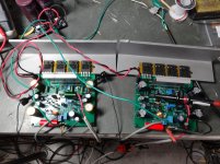
It's singing. I had a bit of a hunt initially because it wouldn't fire up properly. After some measurements and careful inspection I discovered that the indications for the TO-126 transistors have the pinout for a TO-220. The pin designations are correct but character shows the heatsink on the wrong side. This affected Q8 and Q12. Once I spun them around all is good. I'm only pointing this out for others who may build this using these boards. I ran some sine waves and square waves and everything looks good. Only a very slight sign of latching. Not worth worrying about at all. You were right earlier. The power supply I was testing with was sagging more than I realized. I hooked it up to a stiffer supply. Running +-48V at idle, the new supply only drops to +-46.5 at clip which is at 30vac into an 8R load. That's roughly 112W/8R. I don't have a 4R dummy load to test with. I have the bias set to 30V across a pair of the 0,15R emitter resistors which should be 100mA per device. Does this sound about right?
The amp sounds really, really good. Later today I will get it clamped to some good heatsinks and hook it up to my A/B setup and give it some comparisons to some of my other amps. It's very promising right now.
Blessings, Terry
Attachments
OK, I clamped it to some heatsinks and have had it playing for about two hours at a pretty good volume. I had to bump up the bias two or three time before it would stay steady at 100mA. Some of this may be the drivers. They might benefit from a little bigger heatsink. I can just hold onto it. I have it hooked up to my A/B setup and compared it to a Honey Badger and a Peeceebee. It is very close to both. The Peeceebee is lower powered so at higher volume the TT leaves it behind. The HB is as powerful. They are pretty comparable. I won't hesitate to recommend this amp for someone who is looking to try something with Thermaltrak outputs. Very nice!
Blessings, Terry
Blessings, Terry
OK, I clamped it to some heatsinks and have had it playing for about two hours at a pretty good volume. I had to bump up the bias two or three time before it would stay steady at 100mA. Some of this may be the drivers. They might benefit from a little bigger heatsink. I can just hold onto it. I have it hooked up to my A/B setup and compared it to a Honey Badger and a Peeceebee. It is very close to both. The Peeceebee is lower powered so at higher volume the TT leaves it behind. The HB is as powerful. They are pretty comparable. I won't hesitate to recommend this amp for someone who is looking to try something with Thermaltrak outputs. Very nice!
Blessings, Terry
Thank you Terry for your effort to evaluate this amp. About up side down of the Q8 and Q12 I forgot to mentioned that too.
If the amp is overcompensated (if the bias goes down after some heating ) try to increase R35 6k8 one step up. It looks that ONSEMI sometime used TT diode with different tempco in some production. Have you increased R37 from 1k to 6k8 or the latching is still good with 1k?
best wishes
Damir
this is true - charles hansen pointed it out in another post elsewhere a while ago. it was a mfrg mistake.
mlloyd1
mlloyd1
... It looks that ONSEMI sometime used TT diode with different tempco in some production....
Damir
I think it is fine. It probably takes 30 minutes for the bias to settle so for that first 30 minutes the bias is a little high but not too much. There is only a hint of latching. A tiny spike at the tail of the upper flat spot. Not enough to worry about. I will never clip this amp. I suppose someone might if they run really low rails. The only reasons I clip it while testing is it gives me an idea how much power the amp puts out and it will sometime reveal an issue. Same thing with playijg square waves through it. They will kind of show you how the amp behaves but I don't think it has much bearing on how the amp will sound. We pump 100khz square waves though the amp and look at the scope. Most of us can't even hear 20khz, I know I can't. Mine is set up per the schematic. I think I will leave it right there. It sounds wonderful and behaves itself. What more could someone ask for.
Blessings, Terry
Blessings, Terry
I think it is fine. It probably takes 30 minutes for the bias to settle so for that first 30 minutes the bias is a little high but not too much. There is only a hint of latching. A tiny spike at the tail of the upper flat spot. Not enough to worry about. I will never clip this amp. I suppose someone might if they run really low rails. The only reasons I clip it while testing is it gives me an idea how much power the amp puts out and it will sometime reveal an issue. Same thing with playijg square waves through it. They will kind of show you how the amp behaves but I don't think it has much bearing on how the amp will sound. We pump 100khz square waves though the amp and look at the scope. Most of us can't even hear 20khz, I know I can't. Mine is set up per the schematic. I think I will leave it right there. It sounds wonderful and behaves itself. What more could someone ask for.
Blessings, Terry
Yes Terry you are completely right, all that maltreating during different tests is just to "see" how the amp behaves in extreme conditions, but the listening says how it sounds.
By the way this amp is VFA type with Slew Rate of 200V/usec without input filter, not much behind CFA types.
best regards
Damir
that's a good result for your 8r0 test. Just 5.6V loss from quiescent supply rail to full output peak voltage.Running +-48V at idle, the new supply only drops to +-46.5 at clip which is at 30vac into an 8R load. That's roughly 112W/8R.
Do the 4r0 test and if possible also do a 2r7 test to see how well the unclipped output voltage holds up into these high current demand loads. >=28Vac into 4r0 would be good.
>26Vac into 2r7.
These are short term tests, just one or two seconds to read the settled voltage on a DMM and see that the scope shows no clipping.
Last edited:
that's a good result for your 8r0 test. Just 5.6V loss from quiescent supply rail to full output peak voltage.
Do the 4r0 test and if possible also do a 2r7 test to see how well the unclipped output voltage holds up into these high current demand loads. >=28Vac into 4r0 would be good.
>26Vac into 2r7.
These are short term tests, just one or two seconds to read the settled voltage on a DMM and see that the scope shows no clipping.
That are good advices. I apologize for being rude to you Andrew some days ago.
BR Damir
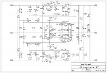
Hi Terry, I suggest you, again, to use my PS Regulator with this amp(or any other amp).
This regulator acts as a capacitance multiplier/regulator, current overload/short circuit protection and a loudspeaker DC offset protection. One PS Regulator board is enough for two TT amp channels, or it could be used two and make dual mono configuration, using one or two transformers. Probably one transformer version is cheaper and equally good and you need only one bank of big caps before the PS Regulators.
I can tell that I use TT amp together with this regulator for years now and a quiet amp became even quieter and more dynamic.
Here is the schematic, the layout and the gerbers.
BR Damir
Attachments

Hi Damir,
nice to see that your design gains constant approval also for its subjective sound quality. Congratulations!
In the past, we had some good discussions about technical details of our designs. Although I'm quite happy with the sound quality of my current design, I feel uneasy because it still is very sensitive to the power supply, namely the type of diodes and the snubbing and mains filtering circuits.
If I understand right, your amp is running in a wooden case without special shielding. Perhaps, the (regulated) power supply is residing in an another case with certain distance. I also read somewhere that you use fast recitfiers (soft recovery or even shottky?).
My question is: did you make listening experiments with different power supplies? You wrote that the regulated power supply leads to a more dynamic impression. Does this already hold for normal, room-listening, levels? Did you experiment with different diodes, and can you say whether your current design is rather sensitive or rather unsensitive agains those influences? Is there a power-supply influence especially on treble reproduction?
Finally: you also designed amplifiers in CFA topology. Can you say, whether these amps behave differently with respect to the power supply (subjective sound quality)?
Kind regards,
Matthias
Hi Damir,
nice to see that your design gains constant approval also for its subjective sound quality. Congratulations!
In the past, we had some good discussions about technical details of our designs. Although I'm quite happy with the sound quality of my current design, I feel uneasy because it still is very sensitive to the power supply, namely the type of diodes and the snubbing and mains filtering circuits.
If I understand right, your amp is running in a wooden case without special shielding. Perhaps, the (regulated) power supply is residing in an another case with certain distance. I also read somewhere that you use fast recitfiers (soft recovery or even shottky?).
My question is: did you make listening experiments with different power supplies? You wrote that the regulated power supply leads to a more dynamic impression. Does this already hold for normal, room-listening, levels? Did you experiment with different diodes, and can you say whether your current design is rather sensitive or rather unsensitive agains those influences? Is there a power-supply influence especially on treble reproduction?
Finally: you also designed amplifiers in CFA topology. Can you say, whether these amps behave differently with respect to the power supply (subjective sound quality)?
Kind regards,
Matthias
Hi Matthias,
First to answer your question about power supply. I use fast switching soft recovery diodes and a snubber parallel to secondary winding only, no individual diode snubbing. I never tried this amp without my PS Regulator, but Terry here used ordinary one(that how I understood) with no hum problem.
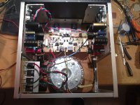
I used wooden case for this amp(for me to expensive to buy full metal case) but with aluminum skeleton, look the photo and the link here. http://www.diyaudio.com/forums/solid-state/182554-thermaltrak-tmc-amp-10.html#post3031504. All power supply parts together with transformer is inside the same box with no hum or noise problem at all, total silence.
So, I used only one power supply type, caps bank of 15000uF per rail and my PS Regulator, did not tried different diodes. I honestly can tell that in my age I could not hear that subtle differences even if tried, so I didn't bother.
And yes, CFA topology, I have now all needed parts and I hope in a week time I would know better what is the difference.
Best regards
Damir
Attachments
Last edited:
Is a pdf pcb version available?Hi Terry, I suggest you, again, to use my PS Regulator with this amp(or any other amp).
This regulator acts as a capacitance multiplier/regulator, current overload/short circuit protection and a loudspeaker DC offset protection. One PS Regulator board is enough for two TT amp channels, or it could be used two and make dual mono configuration, using one or two transformers. Probably one transformer version is cheaper and equally good and you need only one bank of big caps before the PS Regulators.
I can tell that I use TT amp together with this regulator for years now and a quiet amp became even quieter and more dynamic.
Here is the schematic, the layout and the gerbers.
BR Damir
Is a pdf pcb version available?
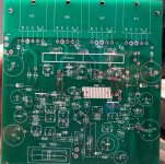
Single side PCB board is here http://www.diyaudio.com/forums/solid-state/182554-thermaltrak-tmc-amp-27.html#post4165464 and follow Terry's progress after that post.
Hi Damir,I used wooden case for this amp(for me to expensive to buy full metal case) but with aluminum skeleton, look the photo and the link here. http://www.diyaudio.com/forums/solid-state/182554-thermaltrak-tmc-amp-10.html#post3031504. All power supply parts together with transformer is inside the same box with no hum or noise problem at all, total silence.
So, I used only one power supply type, caps bank of 15000uF per rail and my PS Regulator, did not tried different diodes. I honestly can tell that in my age I could not hear that subtle differences even if tried, so I didn't bother.
thanks for the info. A nice build.
A completely shielded case (with PSU) probably is difficult. In an experiment some years ago I did not succeed in closing the case without changing the sound to the worse. Assume that HF eddy currents in the case caused the problem. Ther were no apparent hum problems.
Some weeks ago, I tried to change the rectifiers of my current design from simple bridge rectifiers to shottky; there is a lot of rave about it, and for my low-power amp cheap shottky diodes like SB560 are enough.
The subjective result: a little more refined in the treble, but sometimes also tending to mechanical or even harsh sound. Altogether, it is not an improvement.
For my next design, I'm going to use a JFET input and hope to get a more stable result. That also was the reason, why I asked you.
Kind regards and good luck with your next design,
Matthias
Oh sorry dadod i speak for protection board pdfSingle side PCB board is here http://www.diyaudio.com/forums/solid-state/182554-thermaltrak-tmc-amp-27.html#post4165464 and follow Terry's progress after that post.
Oh sorry dadod i speak for protection board pdf
PS Regulator.
Attachments
- Status
- Not open for further replies.
- Home
- Amplifiers
- Solid State
- ThermalTrak+TMC amp