So, should I accept that no one built the honey badger without the cascode/current mirror? It would seem these are only helpful when the rail voltage is below 60V. There should be enough drive in the first stage otherwise. Will someone point me to the spice model of this amp so i can play with it?
The "original"...
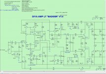
Original "badger' .ASC (spice) and schema.
Current mirror and cascode are 10c parts.
Without the the CM (current mirror) , you lose 20db loop gain and the badger
will become like an internet design. 😀
The cascode really widens your choices for both CM and input pair devices ,
they only have to be >25V devices. The cascode pair handles all the voltage.
If you dropped the cascode , the badger would only lose a few ppm.
-without cascode = 15ppm THD20K .. with= 8-10ppm.
On your other question of using 1 or 2 pair output devices - NO difference
at all other than less SOA for the amp as a whole and the fact that more
pairs will decrease the THD under load.
PS - the Badger would work with just Q1/2 at input , its CLG would be 80db and it would have
.02% thd20k. (R20-21 = 1.5k / no Q3-6) ... TMC (present compensation) would be useless at this gain , as well.
OS
Attachments
Last edited:
Congratulations Bob!
Grandkids are great, you get to send them home after you spoil / play with them. 🙂
My grandkids love me, (too young to know better) and I love them. They all tease me about the mustache, and how it tickles. 😀 Just learned about #4 on the way. Boards still being stuffed......heh.
Glad your feeling up to the outdoors, I've learned a lot from your posts over the years.
Ron
4 times the power theoretically, delivered by 2 amplifier channels in reality.
Amazing how long folks can continue to argue about it.
Bridging TDA2030's, ashaming indeed.
Once had a customer call me a liar when I said that you could get 40V p-p from bridged drivers on +-15 supplies.
Just don't clip. 😉
+1, clipping is an amplitude overload, best to avoid it...sticking usually occurs at the high frequency end of the spectrum, best to avoid it....
besides, the signal is too loud and unpleasant at that point anyway....no need to go there...😉
congrats grandpa Bob....

IPS/VAS capacitance multiplier
Hi All,
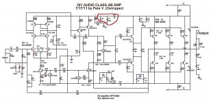
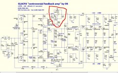
I'm in the planning/purchasing stage of a HB build. One mod I'd like to try is a capacitance multiplier between the OPS rails and the IPS/VAS. I found a well known design 😉 which I'll call "SM" that has what I think is a "drop in" solution. The idea is to omit the HB parts circled in attachment 1, and add the SM parts circled in attachment 2. A little perfboard should be able to handle it using the unpopulated holes in the HB board.
One question. In the SM design, there is an RC stage upstream from the multiplier. Can I safely ignore that ? (There are a couple of loads there in the SM that don't exist in HB).
Also, apart from the R22/R23 ratio, are there any crucial component values in the multiplier circuit ? Anything need to be changed for the HB application ?
Any good reasons why I should NOT do this ?
FWIW, I'm looking at OPS power rails around 42 volts, so 40-ish after the multiplier. (I'm a sonic sissy - no loud music chez moi.)
Thanks
PS #1 No I didn't forget about the negative rail !
PS #2 If this would be better in the build thread, find a kind and gentle way to let me know.
MTA : Although I circled the output bypass cap (HB c10, SM C5) I would physically mount that one on the HB board, not on the perfboard.
Hi All,
I'm in the planning/purchasing stage of a HB build. One mod I'd like to try is a capacitance multiplier between the OPS rails and the IPS/VAS. I found a well known design 😉 which I'll call "SM" that has what I think is a "drop in" solution. The idea is to omit the HB parts circled in attachment 1, and add the SM parts circled in attachment 2. A little perfboard should be able to handle it using the unpopulated holes in the HB board.
One question. In the SM design, there is an RC stage upstream from the multiplier. Can I safely ignore that ? (There are a couple of loads there in the SM that don't exist in HB).
Also, apart from the R22/R23 ratio, are there any crucial component values in the multiplier circuit ? Anything need to be changed for the HB application ?
Any good reasons why I should NOT do this ?
FWIW, I'm looking at OPS power rails around 42 volts, so 40-ish after the multiplier. (I'm a sonic sissy - no loud music chez moi.)
Thanks
PS #1 No I didn't forget about the negative rail !
PS #2 If this would be better in the build thread, find a kind and gentle way to let me know.
MTA : Although I circled the output bypass cap (HB c10, SM C5) I would physically mount that one on the HB board, not on the perfboard.
Attachments
Last edited:
Hi All,
I'm in the planning/purchasing stage of a HB build. One mod I'd like to try is a capacitance multiplier between the OPS rails and the IPS/VAS. I found a well known design 😉 which I'll call "SM" that has what I think is a "drop in" solution. The idea is to omit the HB parts circled in attachment 1, and add the SM parts circled in attachment 2. A little perfboard should be able to handle it using the unpopulated holes in the HB board.
One question. In the SM design, there is an RC stage upstream from the multiplier. Can I safely ignore that ? (There are a couple of loads there in the SM that don't exist in HB).
Also, apart from the R22/R23 ratio, are there any crucial component values in the multiplier circuit ? Anything need to be changed for the HB application ?
Any good reasons why I should NOT do this ?
FWIW, I'm looking at OPS power rails around 42 volts, so 40-ish after the multiplier. (I'm a sonic sissy - no loud music chez moi.)
Thanks
PS #1 No I didn't forget about the negative rail !
PS #2 If this would be better in the build thread, find a kind and gentle way to let me know.
MTA : Although I circled the output bypass cap (HB c10, SM C5) I would physically mount that one on the HB board, not on the perfboard.
The cap multiplier wont hurt anything.
I see you found the simple "slewmaster" cap multiplier.
If you graft one onto the HB , basically R32/33 would be replaced by the
tranny+diode / resistors / multiplied cap. The multiplier output decoupling can
be the onboard HB 220u/.1u's.
You are correct , you will lose 2V .
Multiplier trannies don't need heatsinks , can be any high voltage mje/ksa/c
no high current , even to-92 devices.
multiplier would be device hfe X capacitance. Simple.
Edit- the extra R/C stage is the prediver/driver decoupling ... the SW is a triple (ef3).
Not needed for an EF2 (HB).
OS
Last edited:
Hello all,
I want to build the Honey Badger, but would like to do so with my existing power supply. I recently built an F5 with SIGNIFICANT help from 6L6 (Jim) as we live near each other. Because I already sank a considerable chunk of change into the chassis, transformer and power supply, I would like to just swap out the F5 amp boards for the Honey Badger boards.
My power supply is the standard one using the universal board in the DIYA store (for normal, non-turbo, F5), except my transformer is a hair larger –I get an actual 25 volts per rail.
Will this work with the Honey Badger? If yes, would I have to make any changes to components (transistors, resistors, caps, etc) on the honey badger board?
Also, any idea what the Honey Badger’s power output (watts) would be with only 25 volts?
Thanks in advance – sorry if these are silly questions, I am brand new to this.
-Matt
It will work with the correct resistor changes to get the current values right but there are better choices for that rail voltage.
I simplified this design (drop input cascode, use EFA current mirror. etc) get good result. I use +-45VDC.
Some of my friend compare it with four (more expensive) OEM amplifier, they said my amp have better in mid and high frequency, but have lack deep bass.
Thank you, OS.
Some of my friend compare it with four (more expensive) OEM amplifier, they said my amp have better in mid and high frequency, but have lack deep bass.
Thank you, OS.
I simplified this design (drop input cascode, use EFA current mirror. etc) get good result. I use +-45VDC.
Some of my friend compare it with four (more expensive) OEM amplifier, they said my amp have better in mid and high frequency, but have lack deep bass.
Thank you, OS.
Your welcome , bimo ....
As far as "lacking bass". I don't think so !!
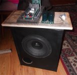
I'm about to put the
'next gen" badger (wolverine) to dedicated sub use (below).
Any badger could also be used in this manner and
put any Dayton plate amp to absolute shame. 😀
Edit - I run a 25HZ sine to verify my woofer/port Fc with this amp -
NO reduced output - even lower <20Hz ... all the way down to 5hz !!
OS
Attachments
Last edited:
Your welcome , bimo ....
As far as "lacking bass". I don't think so !!
OS
Me, too. But I don't know how they compared...
I think this topology has more balance about all aspect, but of course I only built several amp topology and still learn how to design a good amp.
I simplified this design (drop input cascode, use EFA current mirror. etc) get good result. I use +-45VDC.
Some of my friend compare it with four (more expensive) OEM amplifier, they said my amp have better in mid and high frequency, but have lack deep bass.
Thank you, OS.
Double the in- coupling cap--literally I mean 220u||220u (not 220u||100n)
For additional bypass (neither required nor needed), try 10n, not 100n. The result is 220u||220u||10n
Double the in- coupling cap--literally I mean 220u||220u (not 220u||100n)
For additional bypass (neither required nor needed), try 10n, not 100n. The result is 220u||220u||10n
-3dB is around 1Hz. I think the problem is not frequency response. 🙂
Is the "amplifier" capable of -0.01dB at 1Hz?
The input filter determines the passband, IF the amplifier can handle the wide range signal.
Check what is happening inside the amplifier.
If the filter is set to 1Hz and rolls off only 1dB @ 2Hz then you won't hear that as "lacking bass" if the amplifier is reproducing all the signals down to say 5Hz.
But if the amplifier has internal roll offs that start higher at say 50Hz or worse, 150Hz, then one would hear that even with the input filter set that low.
There is another aspect of "amplifier" performance that gives the "effect" of lacking bass. An exaggeration of upper mid and treble frequencies gives the "sound effect" of lower bass. This can be quite subtle in terms of measurement, but can, by comparing the "sound" of amplifier, be very noticeable.
Investigate the "amplifier".
Is the "amplifier" capable of -0.01dB at 1Hz?
The input filter determines the passband, IF the amplifier can handle the wide range signal.
Check what is happening inside the amplifier.
If the filter is set to 1Hz and rolls off only 1dB @ 2Hz then you won't hear that as "lacking bass" if the amplifier is reproducing all the signals down to say 5Hz.
But if the amplifier has internal roll offs that start higher at say 50Hz or worse, 150Hz, then one would hear that even with the input filter set that low.
There is another aspect of "amplifier" performance that gives the "effect" of lacking bass. An exaggeration of upper mid and treble frequencies gives the "sound effect" of lower bass. This can be quite subtle in terms of measurement, but can, by comparing the "sound" of amplifier, be very noticeable.
Investigate the "amplifier".
I ask my friend who compare my amplifier, he said that my amp have short decay in bass. This is what he call lacking deep bass. It is good or not, I do not know, but he think it is not good.
Andrew, I do not understand what you mean "An exaggeration of upper mid and treble frequencies".
But, I do not want to hijacking this thread. If you want help me, please PM me. I just want to show that simplified badger can have good performance. My friend said, it is better than his LM3886. So, may be Honey Badger can give better than mine.
But that is the bass relative to the rest of the audio information.he said that my amp have short decay in bass
The badger/wolverine are VFA. The relative HF phase is shifted in this type amp
versus a fast CFA where there is nearly no shift.
The fastest VFA I have (my spooky leach) , I have to lower the <60hz (it seems
louder). But it's not 😕
It (the leach) tests exactly the same as the badger/wolverine , but it really sounds
different.
Since music is not a "test tone"/signal generator , topology and compensations
have an effect (on music) beyond what can be tested with lab equipment.
PS - my absolute conclusion after swapping badgers, leach's, and various
CFA's into my big amp.
Edit - power supply is a factor , too. All the input stages have a more pronounced
bass when running off 73V rails with 100Kuf.
OS
Last edited:
But that is the bass relative to the rest of the audio information.
The badger/wolverine are VFA. The relative HF phase is shifted in this type amp
versus a fast CFA where there is nearly no shift.
The fastest VFA I have (my spooky leach) , I have to lower the <60hz (it seems
louder). But it's not 😕
It (the leach) tests exactly the same as the badger/wolverine , but it really sounds
different.
Since music is not a "test tone"/signal generator , topology and compensations
have an effect (on music) beyond what can be tested with lab equipment.
PS - my absolute conclusion after swapping badgers, leach's, and various
CFA's into my big amp.
Edit - power supply is a factor , too. All the input stages have a more pronounced
bass when running off 73V rails with 100Kuf.
OS
OS, what topology is the best for bass?
OS, what topology is the best for bass?
I won't denigrate the badger , but I now know why the college student crowd
like the leach amps - party amp - powerful convincing bass !
Could it be the fact that it's symmetrical ? It tests the same , but does not
sound the same. 😕
OS
- Home
- Amplifiers
- Solid State
- diyAB Amp - The "Honey Badger"