Because power GND is a dirty GND
I understand how "lifting" the input ground isolates it from the "dirty" ground. I don't understand how there is any isolation achieved if both are attached to the same star. That is what I am struggling with.
I will try to explain this simple way.I understand how "lifting" the input ground isolates it from the "dirty" ground. I don't understand how there is any isolation achieved if both are attached to the same star. That is what I am struggling with.
Look at pictures ,option 1 & option 2.
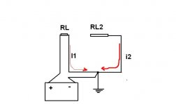
Option 1 separate GND return
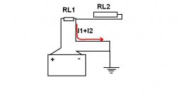
Option 2 common GND retturn.
Attachments
Last edited:

The point that you are missing is that even though it is technically ground, there still is some minute resistance in the wires. Any load that is changing in current draw will impose that signal, a voltage (I*R), upon the finite resistance.
Although this signal is small, if it is amplified, it is both measurable by instruments and your ear using speakers.
Separating ground return paths (dirty/clean) with separate wires minimizes the effect.
A huge copper ground plane with minimal inductance and very low R, does the same thing too.
Although this signal is small, if it is amplified, it is both measurable by instruments and your ear using speakers.
Separating ground return paths (dirty/clean) with separate wires minimizes the effect.
A huge copper ground plane with minimal inductance and very low R, does the same thing too.
Last edited:
I'm not missing that. What you are saying is that a 6" piece of wire will somehow "clean" the dirty ground. I don't believe it.
I do not think that is what I said.
The above picture/schematic shows pictorially what I am saying.
You do not want your signal returns (clean) to share the same wire as one that draws large transient currents(dirty).
The above picture/schematic shows pictorially what I am saying.
You do not want your signal returns (clean) to share the same wire as one that draws large transient currents(dirty).
Maintain rigorously twisted pair for EVERY Flow and Return current.
That is mains current, speaker current, signal current, etc.
Once you have done this, you will be left with telling each part of the amplifier what the signals are referenced to.
These voltage reference wires carry virtually no current, but can carry interference currents.
If possible run these voltage reference wires to your chosen location for the Main Audio Ground (MAG) along the route that their commensurate Flow current is likely to be flowing.
There are very few voltage reference wires in a Power Amplifier.
Signal Return at the front end of the amp, Speaker Return at the output end of the amp, Power ground in the middle of the amp (often this is already linked via the power triplet to the MAG)
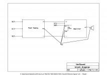
In the diagrams with post395, 400 & 427 I can see that the twisted pairs rule has been broken.
As a result there are single wires emanating from various modules. This leads to confusion and duplication of wiring.
eg
The AC input wiring on the left should be close coupled.
The DC Power wiring in the middle should be close coupled triplet.
The spkr wire on the right should be a close coupled pair.
The last two will meet above the terminal with the 10r resistor.
In a Monoblock that terminal can be the MAG. or the speaker terminal can be nominated as MAG.
In a multichannel amplifier the MAG should be off board.
Now connect the spkr return to MAG
Connect the Signal Return to MAG.
other than Safety connections, the job is done.
If you sort the twisted pairs FIRST, the additional wires become SIMPLE and FEW.
That is mains current, speaker current, signal current, etc.
Once you have done this, you will be left with telling each part of the amplifier what the signals are referenced to.
These voltage reference wires carry virtually no current, but can carry interference currents.
If possible run these voltage reference wires to your chosen location for the Main Audio Ground (MAG) along the route that their commensurate Flow current is likely to be flowing.
There are very few voltage reference wires in a Power Amplifier.
Signal Return at the front end of the amp, Speaker Return at the output end of the amp, Power ground in the middle of the amp (often this is already linked via the power triplet to the MAG)
In the diagrams with post395, 400 & 427 I can see that the twisted pairs rule has been broken.
As a result there are single wires emanating from various modules. This leads to confusion and duplication of wiring.
eg
The AC input wiring on the left should be close coupled.
The DC Power wiring in the middle should be close coupled triplet.
The spkr wire on the right should be a close coupled pair.
The last two will meet above the terminal with the 10r resistor.
In a Monoblock that terminal can be the MAG. or the speaker terminal can be nominated as MAG.
In a multichannel amplifier the MAG should be off board.
Now connect the spkr return to MAG
Connect the Signal Return to MAG.
other than Safety connections, the job is done.
If you sort the twisted pairs FIRST, the additional wires become SIMPLE and FEW.
Last edited:
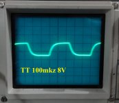
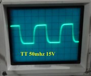
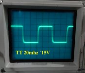
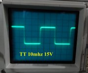
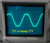
I have good news. I added a BAV21 diode from Q12 collector to Q15 base per Ostrippers' instruction for the Honey Badger which had a similar latching problem. The latching is gone. I have attached some scope shots showing the clipping as well as square waves. The amp begins to clip at about 26vac into an 8 ohm load which calculates to about 85W. A little lower than I was expecting with +-46V rails but more than enough for any listening that I do. If the clamp raised the distortion I can't hear it. The sound if very pleasing with clear highs and mids and solid bass.
I have also attached a shot of the bottom of the board showing how I attached the ground wires. The amp is dead quite right now. I may have to add the ground from input to star if I mount it all in a case, but on the bench it is trouble free,
Blessings, Terry
I have also attached a shot of the bottom of the board showing how I attached the ground wires. The amp is dead quite right now. I may have to add the ground from input to star if I mount it all in a case, but on the bench it is trouble free,
Blessings, Terry
Attachments


Way to go Terry, action speaks louder than words... You make me envy you daily...I wish I could build in the volume and tenacity that you do.
I have good news. I added a BAV21 diode from Q12 collector to Q15 base per Ostrippers' instruction for the Honey Badger which had a similar latching problem. The latching is gone. I have attached some scope shots showing the clipping as well as square waves. The amp begins to clip at about 26vac into an 8 ohm load which calculates to about 85W. A little lower than I was expecting with +-46V rails but more than enough for any listening that I do. If the clamp raised the distortion I can't hear it. The sound if very pleasing with clear highs and mids and solid bass.
I have also attached a shot of the bottom of the board showing how I attached the ground wires. The amp is dead quite right now. I may have to add the ground from input to star if I mount it all in a case, but on the bench it is trouble free,
Blessings, Terry
Very nice Terry,
I would like to show haw simulation shows influence of that diode on THD. At output power of 50W/8, no diode connected THD1k=0.000003%, with BAV21 connected THD1k= 0.000038%, with MMSD4148 very good diode THD1k=0.000036% and ordinary 1N4148 THD1k =0.000221%. It shows THD increase from 12 times to 74 times.
It's really pity to destroy very low distortion(speaking technically) amp with bad diode choice, BAV21 increase THD 12.6 time what is not so bad, but still it's against my technical background.
Did you listen to this amp with diode connected and what is your impression?
If you use +-46 V and you got 26V RMS than your power supply sag during load by 2 volts. With stiffer power suppla you could get 100W with this voltage.
BR Damir
Hi Damir,
Do you really believe you can hear the difference between .000038% and .000003%? I don't believe I can. However I believe I can tell the difference between a speaker that is subjected to the sever latching that this amp has without that diode and a speaker that isn't. If you have a way to stop the latch-up characteristics of this amp that doesn't include that diode I will be happy to try it. I would never install this amp in a cabinet and use it for my everyday amp if I knew my speakers were in danger if someone were to turn up the amp too loud. Pick your poison I suppose.
I did listen to it after the diode was installed. I couldn't hear anything objectionable. I suppose I could pull the diode back out of one side and see if I can detect any sound change. Supposedly, the diode doesn't affect the circuit during normal use and only kicks in when approaching clipping. I never intentionally play an amp loud enough to clip.
As for the output power, you are probably right. The PSU I am using for testing is only a 250VA transformer. I did not check the rails at clipping. It wouldn't surprise me at all if they had sagged 2V. 85W is more than ample. I would be surprised if I ever listen to more than 10w during normal listening.
I will try to get this amp attached to some proper heatsinks and a stiffer power supply sometime this week. I will hook it up to my A/B setup and let compete with some of my other amps. What limited time I've had to listen has been very promising.
Blessings, Terry
ditto
mlloyd1
mlloyd1
Way to go Terry, action speaks louder than words... You make me envy you daily...I wish I could build in the volume and tenacity that you do.
Hi Damir,
Supposedly, the diode doesn't affect the circuit during normal use and only kicks in when approaching clipping. I never intentionally play an amp loud enough to clip.
Blessings, Terry
Hi Terry,
Yes you are probably right about not hearing that level of distortion, but if someone put an effort in the circuit to lower distortion and than increased it 12 times by adding a diode.
The diode affect the circuit exactly in normal operation when is reverse biased, as its reversed capacitance is very non linear and it is parallel to the compensation circuit. Better way is to use Baker clamp, but that requires use separate higher voltage power supply for the IPS.
If you are interested I can show a schematic with it.
As I said before I use regulated power supply with integrated speaker and overcurrent/short circuit protection with this amp.
BR Damir
Hi Damir,
May I ask if this is measured distortion or simulated? What difference does it make if you put one drop of iodine in a swimming pool or twelve if it is still too low to be detected? Isn't it better to have an amp that behaves?
May I ask if this is measured distortion or simulated? What difference does it make if you put one drop of iodine in a swimming pool or twelve if it is still too low to be detected? Isn't it better to have an amp that behaves?
Hi Damir,
May I ask if this is measured distortion or simulated? What difference does it make if you put one drop of iodine in a swimming pool or twelve if it is still too low to be detected? Isn't it better to have an amp that behaves?
OK you can do what you like. Did you tray to increase R37 to 6k8 or 10k?
I have 6k8 there per the schematic. I didn't try 10k. How does that stop the latch up? This amp also doesn't seem to like high frequency square waves. I hear sizzling from 50khz up. Sine waves don't cause it, only squares. I started with the diode because it was easy to install. The board already had pads for it. When I saw that the clipping looked nice I stopped. I don't know if you tried it. I know you said yours latches. The amp sounds very good like this.
Are you seriously expecting your simulation to accurately predict THD at these very low levels?................ simulation shows influence of that diode on THD. At output power of 50W/8, no diode connected THD1k=0.000003%,30ppb, with BAV21 connected THD1k= 0.000038%,380ppb with MMSD4148 very good diode THD1k=0.000036%360ppb and ordinary 1N4148 THD1k =0.000221%.2210ppb..................
Have you achieved <1000ppb THD in any of your amplifiers?
Can you measure <1000ppb THD in ANY amplifier?
Do you have any reasons to suspect the two 4148 results? 360ppb cf 2210ppb
Could the models for these nearly identical diodes be different?
Last edited:
Are you seriously expecting your simulation to accurately predict THD at these very low levels?
Have you achieved <1000ppb THD in any of your amplifiers?
Can you measure <1000ppb THD in ANY amplifier?
Do you have any reasons to suspect the two 4148 results? 360ppb cf 2210ppb
Could the models for these nearly identical diodes be different?
I just wanted to show how a diode influence THD, doesn't matter absolute level . You can compare yourself those two diodes, look for capacitance difference.
- Status
- Not open for further replies.
- Home
- Amplifiers
- Solid State
- ThermalTrak+TMC amp